 Remove
the sparking plug caps and then the cylinder head (rocker box) covers (left)
with the 10mm chromed bolts. Remove the sparking plugs. Note that Valiant's
rocker box covers are sprayed black.
Remove
the sparking plug caps and then the cylinder head (rocker box) covers (left)
with the 10mm chromed bolts. Remove the sparking plugs. Note that Valiant's
rocker box covers are sprayed black.CX/GL 500/650 Cylinder Head / Piston Crown Decoke
This site tells you how to remove the cylinder heads and valves from the engine of your CX/GL, and decoke (decarbonise) them. I am very receptive to comments and suggestions, but you use this information at your own risk.
All the tools, hands and the bike in the article belong to the author.
All nut and bolt sizes are given for the spanner size required to fit them.
Decoking one cylinder head can be done comfortably in an afternoon, although to do them both, you'd have to put in a very full day. I'd recommend taking it easy, and doing the job over a weekend, so you don't feel rushed.
What can go wrong? Unless you find some internal damage such as a burned or bent valve, there isn't much that can go wrong. Your most likely problem is losing one of the small valve collets, or maybe a spring, especially if one manages to "get away" during compression. Even one collet missing will render your cylinder head a useless pile of parts! I'd suggest using an expendable old cotton bedsheet over your work area and hopefully any parts that escape can be found quickly and easily.
During reassembly. you might have the frustration of a stripped engine hanger bolt hole. These can be repaired fairly easily. If you have dodgy bolt holes anyway, repair them at the same time as you do the decoke.
Decoking does not affect engine or valve timing, ignition or carburation. It would be sensible to balance the carburettors afterwards, as following a decoke, the engine should be running more efficiently.
Skill Level : 2. Personally dirty : 2. Work mess : 2. Tools : 1. Space : 1.
Tools : 8mm, 10mm, 14mm ring and socket spanners; feeler gauges; socket ratchet handle and extension arm; rubber mallet; torque wrench; wire brush; "top-end" gasket set; gasket sealant. Newspaper, kitchen roll, lint-free rags. Oil and filter after 500 miles. A pint or so of coolant.
I've recently taken to wearing thin surgical-type rubber gloves during maintenance. These don't last long - I was getting through two pairs a session, but they make a substantial difference to keeping your hands clean. The only warning I'd offer is that you should discard a glove as soon as it tears, as otherwise you might inadvertantly drop a small piece of torn rubber glove into the engine, and block an oilway or water passage.
Special tools : valve spring compressor, valve grinding stick and paste.
Don't attempt this work without a torque wrench as this tool is mandatory when reassembling the cylinder heads.
What is a decoke and why do I need to do it?
1. Accumulation of carbon desposits
As your engine ages, carbon from the burned petrol / air mixture very gradually accumulates on the piston crown, underside of the cylinder head, and on the valves, particularly the exhaust valves. (This is very like plaque building up on your teeth.) Eventually, after anything between 30,000 and 50,000 miles, the seal between the valve rims and the ports in the cylinder head start to degrade and leak, and you get backfiring and a general reduction in performance.
In a severe case, and if left uncorrected, the seal degrades so much that burned exhaust gases are forced past the seal, causing major (probably fatal) valve and cylinder head damage.
Using an upper cylinder lubricant such as Redex does stave off the inevitable accumulation of carbon and I recommend using it every fourth or fifth tankful.
2. Blown head gasket
The thick cylinder head gasket between the head and the barrel not only seals that joint, containing the force of the mixture exploding, it also ensures that the lubricating oil and the coolant do not leak between their passages, as they are pumped round the engine. If the cylinder head gasket blows, there is probably a leakage of these fluids into the inside of the engine, without external evidence. Also, engine oil may leak into the cooling system and cause blockages. The head gasket is therefore under considerable pressures.
The most common symptoms of a blown head gasket are:-
> white scum or froth on the oil surface, easily seen on the dipstick and indicating leakage of coolant into the lubrication system. This is the classic symptom;
> oil scum seen floating on the surface of the coolant, when the radiator cap is removed for checking the liquid level, and indicting a leakage of oil into the cooling system;
> both these symptoms;
> loss of oil and / or coolant with no apparent reason, no external leakage;
> reduction in performance as compression is lost between the cylinder head and barrel
> black exhaust stains between the cylinder head and barrel.
In both cases, decoking the heads and valves is a simple enough job requiring only one specialised tool apart from a valve grinding stick, which is a wooden pole about 8 inches long with a rubber sucker at each end, and costing only a few pounds from your tools dealer. You will also need a tube (like a toothpaste tube) of both coarse and fine valve grinding paste, again readily and cheaply obtained from any tools or spares shop.
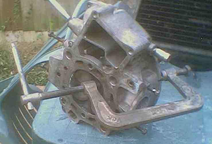
The specialised tool required is a valve spring compressor, again a fairly standard purchase from a tool dealer. I use a very simple one like a carpenter's G-cramp. You cannot remove cylinder head valves without this tool.
You don't need to remove the engine from the frame.
In the photographs, you will see that Valiant's engine is removed, because it was out anyway for other work. But you will actually find it easier to do the decoke with your engine in place.
Park the bike on a secure surface and switch off the ignition. You don't need to disconnect the battery, but you can if you wish.
Remove the fuel tank as per the first section of this web page. Remove the saddle and side panels. One upturned side panel makes a useful place to keep stray nuts and bolts.
Remove the carburettors and inlet tracts as per this web page. Don't completely disconnect the carbs; just leave them on the end of the throttle cables, and swing them onto the top of the main spar. Beware petrol leakage at this point.
There is no need to drain the engine oil, but you should drain the coolant as per this web page. Have a new oil filter and new oil ready as you will need to do an oil and filter change 500 miles after the engine is rebuilt.
This procedure applies to each cylinder head in turn. Only work on one side at a time so there is no danger of intermixing the components.
On the right hand cylinder head, remove the two 10mm nuts and washers which bolt the exhaust manifold ring to the cylinder head. Slide the ring down the exhaust pipe. Where the other end of the exhaust pipe meets the exhaust collector box (commonly called the H-Box) under the engine, slacken the 12mm chrome clamp bolt and then wriggle the exhaust pipe clear. At the H-box end is a fragile asbestos sealing ring, take care not to lose or damage this. It may either come off with the exhaust pipe, or stay inside the H-Box.
If your bike has a Motad type 2:1 or one-piece aftermarket exhaust, you may have to remove the entire exhaust system. If you have standard 2:2 exhausts and silencers, you don't need to unbolt the silencers.
Now peer inside the sooty exhaust port, and dig out the squashed copper crush gasket. These can be hard to spot as they look as if they are part of the cast aluminium head. Scrape gently with the tip of a screwdriver and if you get copper shavings, dig deeper and drag out the flattened sealing ring. This will need replacing.
Remove
the sparking plug caps and then the cylinder head (rocker box) covers (left)
with the 10mm chromed bolts. Remove the sparking plugs. Note that Valiant's
rocker box covers are sprayed black.
Remove the flywheel inspection port as per this web page, and rotate the crankshaft until all 4 valves are closed (both rocker arms can be moved fractionally by hand) with TR on the alignment mark.
 Remove
the two 10mm head bolts (right) which hold the rubber heat shield in place.
Remove
the two 10mm head bolts (right) which hold the rubber heat shield in place.
 Remove
the two 8mm head bolts (left) which attach the water transfer pipe, and dislodge
the pipe. A minor coolant leak is likely at this point. Discard the O rings
and clean up the mating surfaces of the pipe and its junction.
Remove
the two 8mm head bolts (left) which attach the water transfer pipe, and dislodge
the pipe. A minor coolant leak is likely at this point. Discard the O rings
and clean up the mating surfaces of the pipe and its junction.
Pull off the thick rubber breather pipe, if fitted (CX500 and CX500A) to the right hand cylinder head.
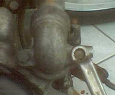
Normally the engine hanger (or A-frame) is retained against the engine by 2 steel studs on each side of the engine. One end of the stud screws into the aluminium engine and there is a nut on the other end. Bikes with engine crash bars will probably have the longer 14mm head bolts as per the photo opposite.
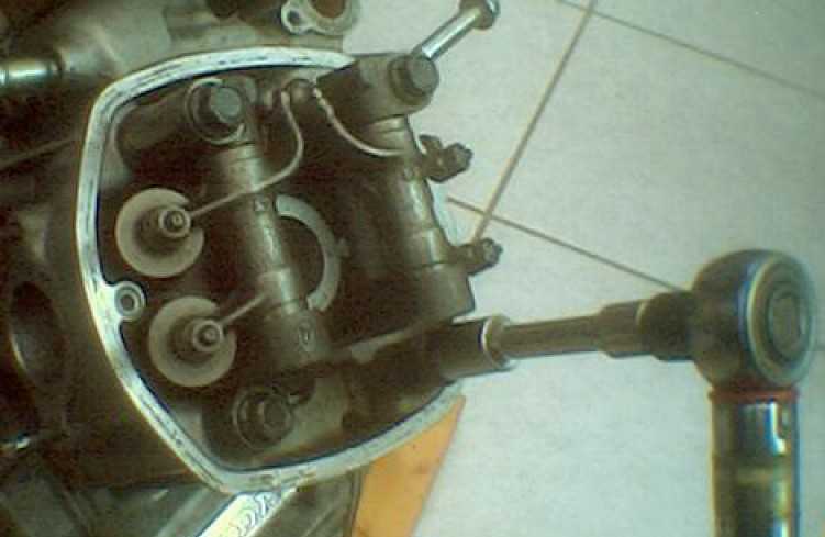
 If
you have the bolts like the photo opposite, you need only remove the
topmost engine hanger bolt (right) with the 14mm head. You may have to unbolt
or loosen any engine crash protectors, and temporarily remove the radiator shroud,
if there is not enough clearance to get the big bolt out.
If
you have the bolts like the photo opposite, you need only remove the
topmost engine hanger bolt (right) with the 14mm head. You may have to unbolt
or loosen any engine crash protectors, and temporarily remove the radiator shroud,
if there is not enough clearance to get the big bolt out.
However if you have the long studs ... you have no option but to support the engine from underneath whilst you unbolt and remove the A-frame (or engine hanger) by unfastening the two long bolts at the top of the main spar, and then sliding the A-frame forwards, off the studs. Sometimes you can get a wrench on the unthreaded part of the stud and unscrew it, but usually these studs are corroded up and won't easily come out. Only when the hanger has gone far enough forward to clear all 4 studs, is there enough clearance to get the cylinder head off. So it's probably worth removing all 4 studs and sourcing 4 of the 14mm head bolts, as these are much easier to get out in the future.
You may have to drain the radiator and completely remove it, if there is not enough clearance on the studs.
If you are unfortunate enough to strip a thread, see this page on thread repairs. For the replacement bolts, try a local tool supplier or, a bike breaker.
At the lower front of the barrel is a 10mm short bolt which allows coolant in the cylinder jackets to drain. Remove this and replace it when the small amount of coolant has escaped.
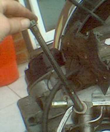 Note
the black 14mm black high tension cylinder head bolts (left) at each corner
of the head. Loosen them a sixteenth of a turn in the sequence : top left >
bottom right > top right > bottom left. Loosen them another half turn
in the same sequence and continue to do this until they are free enough to be
undone by hand.
Note
the black 14mm black high tension cylinder head bolts (left) at each corner
of the head. Loosen them a sixteenth of a turn in the sequence : top left >
bottom right > top right > bottom left. Loosen them another half turn
in the same sequence and continue to do this until they are free enough to be
undone by hand.
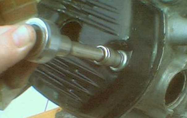
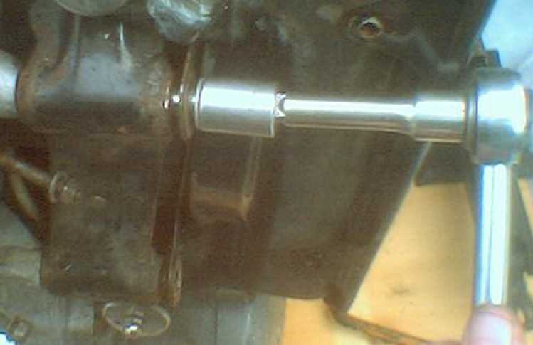
The black bolts are surprisingly long (right). When they come free, there is usually a distinct popping sound as oil suction is broken, this is normal.
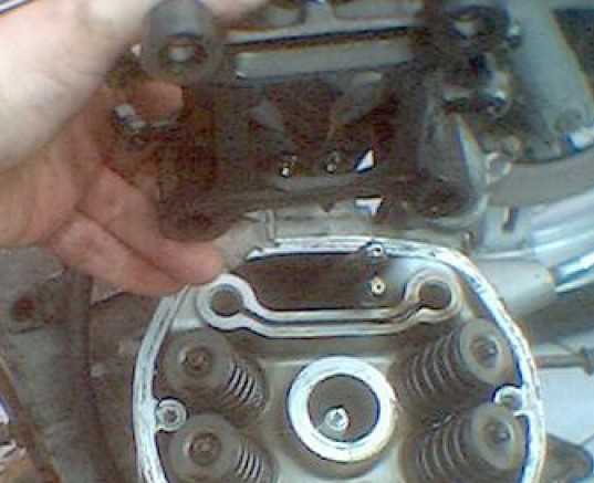 With
all 4 black bolts removed, pull or gently prise off the rocker arm mechanism
(left), this is in one piece. Don't lose the two large hollow locating dowels
which fit between the rocker mechanism and the cylinder head.
With
all 4 black bolts removed, pull or gently prise off the rocker arm mechanism
(left), this is in one piece. Don't lose the two large hollow locating dowels
which fit between the rocker mechanism and the cylinder head.
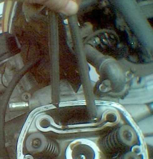 Pull
out the rocker arm pushrods (right). These only rest in place and are not attached
in any way.
Pull
out the rocker arm pushrods (right). These only rest in place and are not attached
in any way.
Some cylinder heads come straight off and some are extremely stubborn. Give the head some firm strokes with a rubber mallet, or with a wooden block between a hammer and the head, and work round all sides, giving sharp strokes to loosen the join.
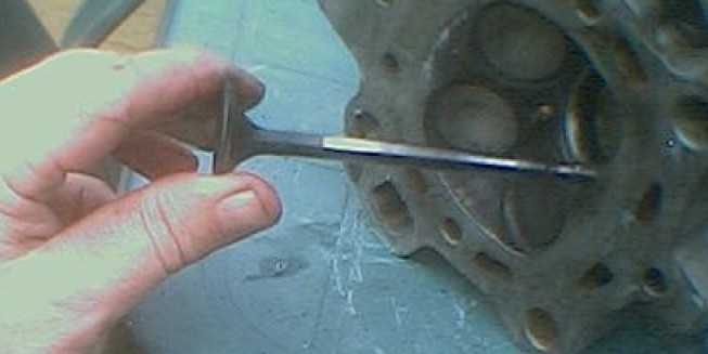
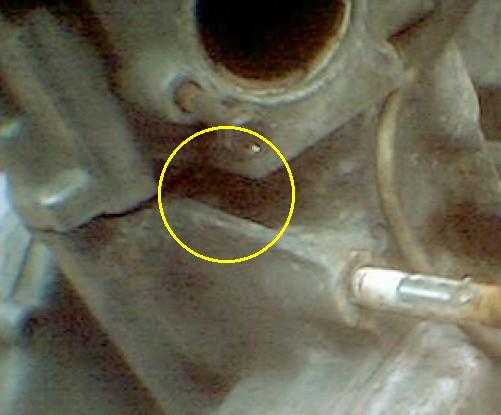 I've
found it best to use a large broad bladed screwdriver (left) at the place ringed
(right), and gently tease the head off the barrel.
I've
found it best to use a large broad bladed screwdriver (left) at the place ringed
(right), and gently tease the head off the barrel.
Don't force a blade between the two mating surfaces as they open, or you may well damage the faces. As soon as the gap opens, the head should pull off without problems. Don't worry about damaging the gasket, as you will be discarding it.
In the top rear corner of the mating surfaces on the barrel, you will see a small oil jet. Retrieve this and store it safely, discarding the (usually green) O-ring around it.
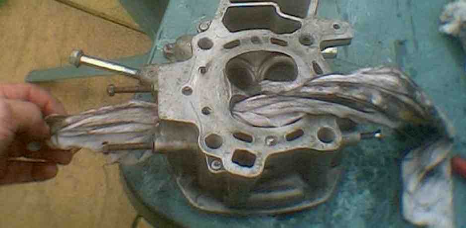
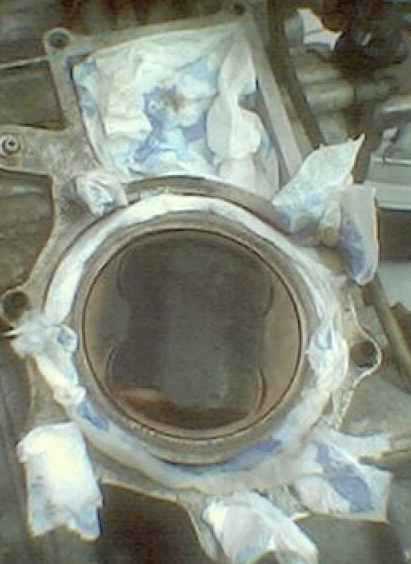 Plug
the orifices in the exposed barrel with lint free rag, newspaper, or kitchen
roll (left), to prevent foreign objects from falling in, and cover the exposed
engine with an old towel, or cloth, whilst work is carried out on the removed
cylinder head.
Plug
the orifices in the exposed barrel with lint free rag, newspaper, or kitchen
roll (left), to prevent foreign objects from falling in, and cover the exposed
engine with an old towel, or cloth, whilst work is carried out on the removed
cylinder head.
Note the carbonised piston crown. This will get cleaned up and polished later.
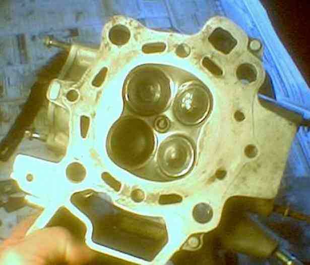
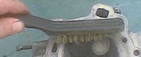 Place
the upturned cylinder head on a workbench (right) and use a wire brush to clean
off surface dirt and debris. It's worth making a thorough job of this, as it
saves time later on. As dirt is removed, blow it clear of the head. Particularly,
use a soft scraper (I use an old thick feeler gauge) to scrape off all traces
of any gasket or sealing compound.
Place
the upturned cylinder head on a workbench (right) and use a wire brush to clean
off surface dirt and debris. It's worth making a thorough job of this, as it
saves time later on. As dirt is removed, blow it clear of the head. Particularly,
use a soft scraper (I use an old thick feeler gauge) to scrape off all traces
of any gasket or sealing compound.
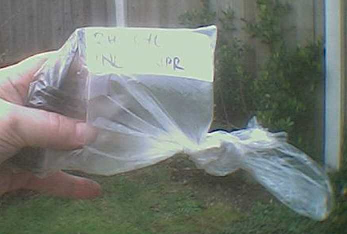
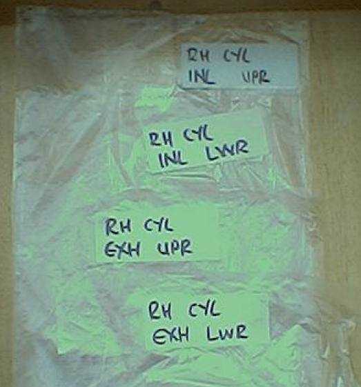 As
the valves and their component parts should not be intermixed, prepare 4 labelled
clear plastic sandwich bags (left) ready to hold each set of valves as they
are removed.
As
the valves and their component parts should not be intermixed, prepare 4 labelled
clear plastic sandwich bags (left) ready to hold each set of valves as they
are removed.
Each valve is inserted from the combustion chamber (underside, or piston area) and has a round steel base, an inner and outer spring, a steel collar and two half-moon-shaped collets. The collets slot into a groove in the top of the valve stem and are retained in place by the upwards pressure from the springs against the shaped collar. In order to remove the collets, a spring compressor is used to compress the springs, exposing the collets which then either fall out or are poked free.
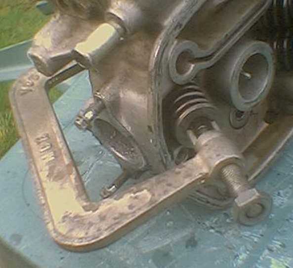
 Attach
your valve spring compressor (left) to one valve, and compress its springs.
I had a very mild day at the end of February 2003 and was able to work outside
on the garden table - quite remarkable for February in Shropshire!
Attach
your valve spring compressor (left) to one valve, and compress its springs.
I had a very mild day at the end of February 2003 and was able to work outside
on the garden table - quite remarkable for February in Shropshire!
 Don't
get your fingers near the compressed mechanism, as if it slips off, you may
get a bad injury to a fingertip.
Don't
get your fingers near the compressed mechanism, as if it slips off, you may
get a bad injury to a fingertip.
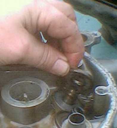
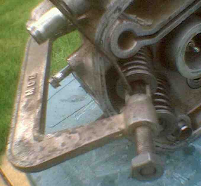 When
the pair of valve collets are exposed (left), use a thin bladed screwdriver
to poke them off the top of the valve stem. Relax the compressor, and remove
it.
When
the pair of valve collets are exposed (left), use a thin bladed screwdriver
to poke them off the top of the valve stem. Relax the compressor, and remove
it.
 Slide
off the spring collar and then the inner and outer springs (right)
Slide
off the spring collar and then the inner and outer springs (right)
 Push the valve stem (left) through "downwards" and remove it. Pull
off the valve seat. Store each set of valves in the labelled plastic bag, and
tie the neck.
Push the valve stem (left) through "downwards" and remove it. Pull
off the valve seat. Store each set of valves in the labelled plastic bag, and
tie the neck.
If the valve is twisted, bent or warped, or if it has a burned-away part, replace it.
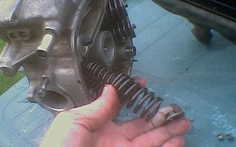
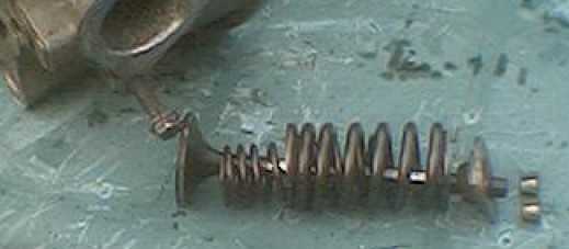 Repeat
with the other three valves. Photo (right) shows the valve and spring assembly.
Note that the valve's base ring hasn't been removed from the head yet, and isn't
shown here.
Repeat
with the other three valves. Photo (right) shows the valve and spring assembly.
Note that the valve's base ring hasn't been removed from the head yet, and isn't
shown here.
 Bag
each set of valve components as you remove them, as they shouldn't be intermixed.
Bag
each set of valve components as you remove them, as they shouldn't be intermixed.
 Pull
off each valve stem seal (right) and discard it. These tend to go crumbly or
hard, and disintegrate as soon as you grab them with a pair of pliers. Be sure
to remove all accumulated debris.
Pull
off each valve stem seal (right) and discard it. These tend to go crumbly or
hard, and disintegrate as soon as you grab them with a pair of pliers. Be sure
to remove all accumulated debris.
 Pull
off each valve seating ring and store these safely. It is ok to intermix these.
Pull
off each valve seating ring and store these safely. It is ok to intermix these.
The next step is somewhat tedious and is best done to your favourite video ... place the upturned head on a firm surface and use a soft scraper (again, a thick feeler gauge is ideal) to completely remove all accumulated black carbon deposits from the inside of the cylinder head and the 4 ports. A good deal of black dust and muck results, which should be regularly blown clear. After an hour or two of scraping, use a metal polish and a soft cloth to buff up the combustion chamber surfaces as brightly as possible. The shinier the metal, the less easy it is for carbon to begin accumulating all over again.
 You
can never get the metal looking new, but get it as clean and bright as you can.
You can use a toothbrush to good effect to reach down into the exhaust ports,
and run a cleaning rag to-and-fro to get the carbon out.
You
can never get the metal looking new, but get it as clean and bright as you can.
You can use a toothbrush to good effect to reach down into the exhaust ports,
and run a cleaning rag to-and-fro to get the carbon out.
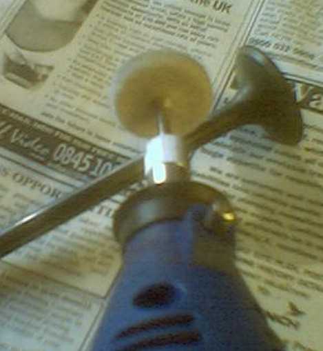 I
used a Focus DIY electric variable-speed hand tool (left) with a buffing wheel
to clean the cylinder heads and valves. Where carbon was particularly hard,
I used an abrasive wheel VERY CAREFULLY AND GENTLY so as not to
damage the actual metal. Focus DIY's tool is like a Dremel but 1/4 of the cost
(£20 against £80), and it saved me hours of work, particularly on
the polishing.
I
used a Focus DIY electric variable-speed hand tool (left) with a buffing wheel
to clean the cylinder heads and valves. Where carbon was particularly hard,
I used an abrasive wheel VERY CAREFULLY AND GENTLY so as not to
damage the actual metal. Focus DIY's tool is like a Dremel but 1/4 of the cost
(£20 against £80), and it saved me hours of work, particularly on
the polishing.
This is a good time to clean up the cylinder head external casing as well. Opinions differ widely on the best way to get a really good finish, but one cheap and easy, but time consuming way, is a fingertip of Solvol Autosol (or other aluminium-suitable metal polish) rubbed well in, and then buffed up with a soft cloth. It takes a long time, but it's worth the effort.
If you are lucky enough to have access to bead blasting equipment, the whole job is dead easy and done in a minute or two. However - be extremely careful to ensure that all traces of the bead blasting compound are flushed out afterwards. If any of this very abrasive compound gets into the oil system, your engine will be wrecked in no time at all (don't ask me how I know this ...).
Then take each valve in turn from its bag and clean and polish it in the same way, removing all traces of accumulated carbon from the stem and valve underside. Inlet valves in particlar seem to get a very hard dull white calcium-like deposit which can be hard work to scrape off.
Valve Grinding
Each cleaned-up valve in turn now has its mating face ground to exactly match the seating in the cylinder head. This ensures a perfect seal when the valve closes.
 Take
the first valve and lightly oil the stem. Smear a small amount of "coarse"
valve grinding paste (left) over the sealing face of the valve and insert it
into the correct port in the cylinder head. Take care not to make a mistake
as the valves should not be intermixed.
Take
the first valve and lightly oil the stem. Smear a small amount of "coarse"
valve grinding paste (left) over the sealing face of the valve and insert it
into the correct port in the cylinder head. Take care not to make a mistake
as the valves should not be intermixed.
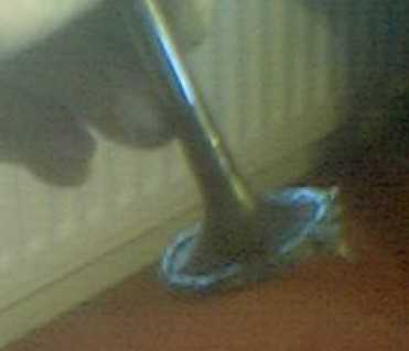
 Apply
the valve grinding stick's rubber sucker to the valve's underside (right) and
rolling the stick between the palms of your hands with a downwards pressure,
firmly rotate the valve against the cylinder head. Lift the valve partially
out again and turn it 90 degrees. Repeat this process, occasionally wiping the
valve clean and applying further coarse paste, until the mating surface of both
the valve and the cylinder head show a 1/10" or 2mm wide unbroken dull
matt face.
Apply
the valve grinding stick's rubber sucker to the valve's underside (right) and
rolling the stick between the palms of your hands with a downwards pressure,
firmly rotate the valve against the cylinder head. Lift the valve partially
out again and turn it 90 degrees. Repeat this process, occasionally wiping the
valve clean and applying further coarse paste, until the mating surface of both
the valve and the cylinder head show a 1/10" or 2mm wide unbroken dull
matt face.
Clean the valve and head of the coarse paste and apply "fine" valve grinding paste to the valve seat. Continue with this process until the mating surface between the valve and cylinder head is quite smooth continuous. Thoroughly clean away all traces of grinding paste and replace the valve's steel footplate over the valve guide. Press on a new valve seal and reinsert the valve.
With the close-coiled springs against the steel footplate, replace both inner and outer springs and then the retaining plate. Have the valve collets close to hand and use the valve spring compressor to compress the springs until the collets can be inserted and the spring compressor relaxed.
CAUTION! Sometimes the spring compressor slips off the valve spring retaining plate and the various parts will shoot off at very high speed. Don't get your eyes or fingers so positioned that an injury might result, and don't sit where a window might be broken by flying steel components!
To check that the collets are correctly seated after removing the compressor, give the valve stem a sharp knock with a hammer, along the downwards line of the valve stem. After the valve springs have rebounded, the collets should not have moved.
To test the integrity of the freshly ground-in mating faces, squirt in some WD40, or pour in a teaspoonsful of petrol or paraffin from the exhaust or inlet port, there should be no leakage past the valve seat into the combustion chamber area. If there is, remove the valve and regrind a little more, using fine paste.
Repeat this with the other three valves.
 Nice
clean and shiny cylinder head and valves, after reassembly
Nice
clean and shiny cylinder head and valves, after reassembly
If repeated attempts to make a perfect seal are resulting in substantial grinding, the cylinder head should be either replaced, or entrusted to a specialist machine shop to have the seating face re-cut. In this case, new valves will be needed.
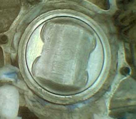 Use
a similar technique to remove carbon from the tops of the exposed piston, and
take care that debris does not fall into the engine. Polish the piston crowns
to a good bright finish (right). Thoroughly remove all traces of the old head
gasket.
Use
a similar technique to remove carbon from the tops of the exposed piston, and
take care that debris does not fall into the engine. Polish the piston crowns
to a good bright finish (right). Thoroughly remove all traces of the old head
gasket.
Refitting the cylinder head
Double check that the head is quite clean and free of debris, lint, especially that all grinding paste has been removed. It is very abrasive and will damage the engine if allowed to contaminate the oil supply. Clean the mating surfaces of the barrels.
Have ready : a new head gasket with a the small O rings that sit over the oil feed jets between the barrels and the cylinder heads, plus some gasket sealant (I use Hylomar).
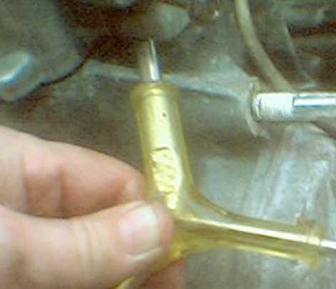
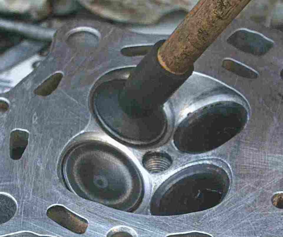
 Fit
the oil jet (left), indicated by the tip of the screwdriver..
Fit
the oil jet (left), indicated by the tip of the screwdriver..
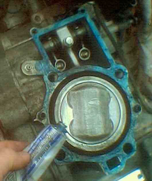 Smear
gasket sealant (right) over the mating surface of the barrel, and position the
gasket. Fit the oil jet's O-ring and don't get any gasket sealant into the oil
jet.
Smear
gasket sealant (right) over the mating surface of the barrel, and position the
gasket. Fit the oil jet's O-ring and don't get any gasket sealant into the oil
jet.
 Smear
gasket cement over the mating surface of the cylinder head and position it over
the gasket, where it it located by two steel dowels (left). Push the head into
place checking that the gasket is correctly placed.
Smear
gasket cement over the mating surface of the cylinder head and position it over
the gasket, where it it located by two steel dowels (left). Push the head into
place checking that the gasket is correctly placed.
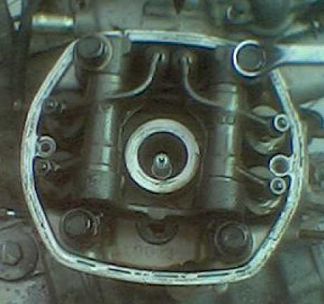
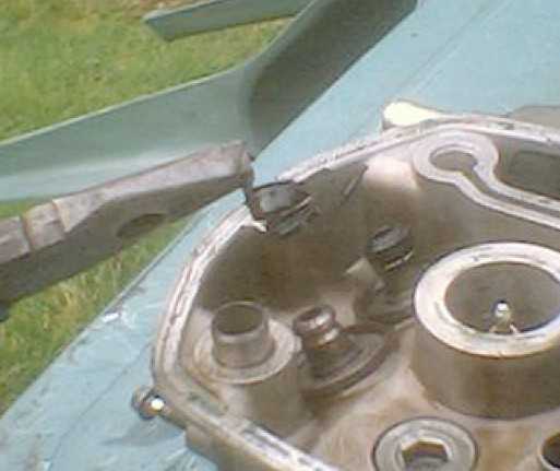
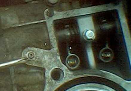
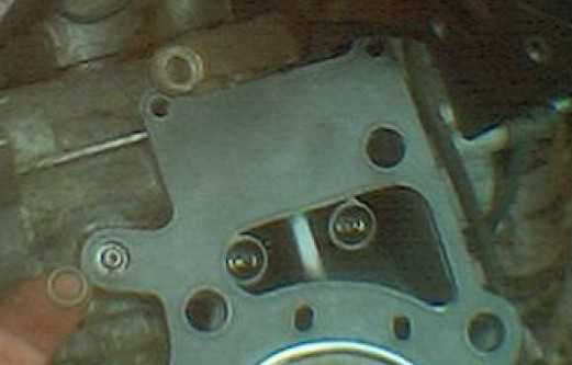
 Dab
a spot of grease onto the end of each pushrod and slide them into their sockets
inside the engine (right). It's worth double checking that these are firmly
in place. Here, the right hand one is in place and you can see the socket for
the left hand one. Note that in this picture, the head gasket is not present.
Dab
a spot of grease onto the end of each pushrod and slide them into their sockets
inside the engine (right). It's worth double checking that these are firmly
in place. Here, the right hand one is in place and you can see the socket for
the left hand one. Note that in this picture, the head gasket is not present.
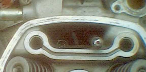
The "trough" is the oil feed passageway for the rocker mechanism. Don't obstruct this, as oil is pumped up the passage where the cylinder head bolts go, and the trough then shares it with the other side of the cylinder head.
Using a 17mm socket on the crankshaft nut on the front casing just above the clutch, rotate the crankshaft to bring the right cylinder to top dead centre (view TR through the timing aperture on the rear crankcase). Don't worry about whether this is TDC on the exhaust or inlet stroke ... you haven't fitted the cylinder head yet, so it doesn't matter.
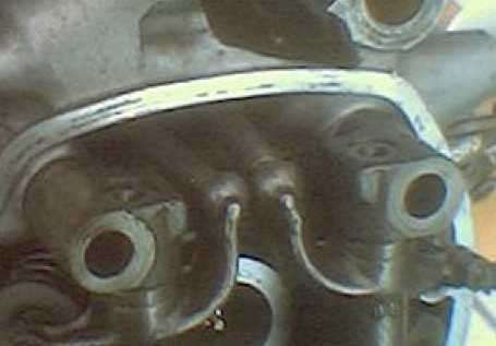 Locate
the rocker arm mechanism onto its two big dowels in the cylinder head, and ensure
that the top ends of the pushrods are located in their corresponding sockets
on the rocker mechanism (left). You may have to tap the rocker mechanism with
a rubber mallet to get it to drop into place.
Locate
the rocker arm mechanism onto its two big dowels in the cylinder head, and ensure
that the top ends of the pushrods are located in their corresponding sockets
on the rocker mechanism (left). You may have to tap the rocker mechanism with
a rubber mallet to get it to drop into place.
Insert the four long black cylinder head retaining bolts and screw them finger tight.
If you haven't got a torque wrench, stop working now and go and buy one. I know I'm paranoid about torque wrenches, but:-
DON'T EVEN THINK ABOUT COMPLETING THE NEXT STEP WITHOUT USING A TORQUE WRENCH!
If you try and tighten the head bolts "by feel", you may well cause fatal damage to your engine. If you overtighten the bolts, the least inconvenient thing that can happen is that one shears off. If you are lucky, it will shear at the head and all that will be needed is to remove the cylinder head, extract the broken-off bolt and replace it. If you are unlucky, it will shear flush with the top of the barrel and to extact this stub will take considerable effort and ingenuity. If this happens to you, well jolly well serve you right, try chiselling a slot in the top of the body of the bolt, taking great care not to damage the threads of the aluminium barrel, and then teasing the stub out with a screwdriver or slim chisel and rubber hammer. This will take several hours of slow, frustrating, patient effort.
More likely is that the screw threads cut into the aluminium barrel will strip out. If this happens, you have no choice but to take the engine to a specialised engineering workshop and have the old hole drilled out to oversize, a plug inserted and the plug drilled and tapped back to the original size. If you are seriously unlucky, the barrel casting will break. This means a new crankcase and a full engine stripdown.
IT'S JUST NOT WORTH THE RISK - USE A TORQUE WRENCH!
In a diagonal sequence top right > bottom left > top left > bottom right, tighten the four head bolts in several stages:-
 First
to 15 ft/lbs, then to 25 ft/lbs.
First
to 15 ft/lbs, then to 25 ft/lbs.
Finally, for all 500cc (except GL), tighten to 36 - 40 ft lbs.
or
For all 650cc and GL500, tighten to 36 - 43 ft lbs.
Reconnect the water transfer passages from the thermostat area under the main spar. The two 8mm holding bolts should not be tightened more than 6 ft/lbs and use new O-rings. I also recommend a gasket sealant at each end of the short transfer pipes.
Replace the two 10mm head bolts holding the heat shield to the cylinder head, tighten not more than 9 ft/bs.
Use a new copper crush gasket inside exhaust port, between the cylinder head and the top of the exhaust downpipe. Refit the exhaust header downpipe and manifold ring, tightening the 10mm nuts to 6-9 ft/lbs and then the chrome H-box clamps to 9-14 ft lbs. If you damage the asbestos sealing ring, you can wrap a couple of layers of silver exhaust bandage or even kitchen foil around it before reassembly.
Repeat the entire replacement procedure with the other cylinder head, using "TL" as the timing mark for top dead centre.
I recommend tightening to the lowest maximum figure (36 ft/lbs in all cases) and then retightening to the midrange once the engine has been run and tested.
Reset the valve clearances, replace the rocker box covers and test the engine. Do not rev it hard but allow it to settle down before gentle road use and a check for leaks. After 500 miles, replace the oil and filter and check the valve clearances again, especially if they are rattling. They will "bed in" and need adjusting again quite soon.
Decoking does not affect engine or valve timing, ignition or carburation. It would be sensible to balance the carburettors afterwards, as following a decoke, the engine should be running more efficiently.
You are welcome to comment on these pages.