CX500
/ GL 500 / CX650 / GL650
Tappets
(Valve Clearances) and Cam Chain Adjustment; clean / reset Sparking Plugs
Skill
levels explained.
Skill Level : 2. Dirty
Level : 1. Mess Level : 1. Tools level : 1 : 10mm, 12mm ring
and socket spanners; ratchet and extension bar; torque
wrench; feeler gauges; spark plug removal wrench; slim nosed pliers;
wire brush; a hand lamp may also help. Space required : 1
Time : expert 15 minutes,
average 20 minutes, "first-time" 40 minutes.
All the hands, tools, and bike in
the photos are the author's.
All nut
and bolt sizes are given as the spanner size required to fit them.
I am very receptive to comments and
suggestions, but you use these pages entirely at your own risk.
This page will show you how to check
and adjust the valve clearances (tappets) and the manual cam chain adjustment
on your Honda CX500, and variants, engine. If you own a "Eurosport"
CX500E-C, GL500, or any of the 650cc or Turbo models, your cam chain
tensioner is fully automatic, and you don't have to routinely do anything to
it.
The CX engine's cylinder heads project
well clear of the petrol tank and main spar and consequently there is nothing
to dampen or mask the sound of clicking or clacking tappets. This makes the
CX rider extremely aware of when things are in need of adjustment, especially
when filtering past stationary traffic and the engine sound is reflected back
from the sides of adjacent vehicles.
Tappet and cam chain adjustment is
simple and can be done whenever desired; Honda recommend that the procedure
is carried out as a matter of routine every 7,200 miles (12,000 km) for UK
500s, UK 650s, and all US models up to 1981; and every 8,000 miles (12,800
km) for other models. In practice I have found it necessary to adjust the
tappets very much more frequently than that, even as often as every 2,000 miles,
or the rattle becomes annoying, especially as the bike inexorably ages. However
the "normal" tappet rattle doesn't do any harm, but a pronounced clattering
should be dealt with immediately. You can even do this by the side of the road,
if your travelling toolkit is up to it, and you allow your engine to cool.
Procedure
Note that the engine should
be absolutely stone cold; best left overnight in fact. Some Honda engines
have the cam chains adjusted whilst the engine is running, but the CX does not.
Place the bike on its centre stand on a firm surface and turn off the ignition.
As you will be dealing with petrol, don't smoke or use any naked flame during
this procedure.
 Turn
off the fuel supply and disconnect the fuel pipe from the petrol tank to the
LH carburettor. My bike has a manual fuel tap with only one pipe, but variants
with a vacuum operated tap will have two pipes. Remove the saddle. My bike has
two spring loaded catches at each underside of the rearmost part of the saddle;
other models may be different, and require the saddle to be unbolted.
Turn
off the fuel supply and disconnect the fuel pipe from the petrol tank to the
LH carburettor. My bike has a manual fuel tap with only one pipe, but variants
with a vacuum operated tap will have two pipes. Remove the saddle. My bike has
two spring loaded catches at each underside of the rearmost part of the saddle;
other models may be different, and require the saddle to be unbolted.
Remove the 12mm head bolt securing
the petrol tank, and lift off the tank. Some variants have the tank bolted at
two points right at the front. Place the tank outside and away from any potential
source of heat, flame or electrical spark. Particularly, if you are working
in a shed or garage, do not place it at your only means of exit. If there is
a fire, you won't be able to escape. I was once trapped in this way and ended
up with very nasty burns to one leg.
 Pull
off both long sparking plug caps from the plugs, then remove both plugs, putting
them safely aside if you plan to reuse them. Note that the plugs are unusually
deeply recessed and a long reach plug spanner will be needed to get to them.
Pull
off both long sparking plug caps from the plugs, then remove both plugs, putting
them safely aside if you plan to reuse them. Note that the plugs are unusually
deeply recessed and a long reach plug spanner will be needed to get to them.
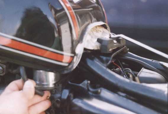
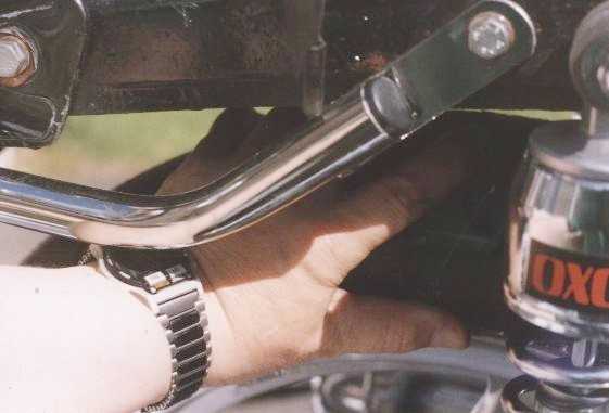
The chromed curvy bar at the bottom
left of the picture is part of the engine protectors. You can also see the chrome
water transfer pipe which feeds water between the water pump at the rear top
of the engine, and the radiator right at the front. The aluminium L-shaped section
at 11 o'clock in the picture is the water transfer pipe between the left cylinder
jacketing and the thermostat. It's a good idea to give these parts a good visual
check for leaks, whilst you are there, and to brush out any dust or dirt from
the crankcase area underneath the petrol tank.
 Remove
the two 10mm chromed securing bolts and then the RH cylinder head rocker box
cover. My bike has had these covers sprayed black. The rocker box covers may
need a firm tap with a rubber hammer to dislodge them. Repeat with LH cover.
Notice the exposed mechanism; rocker arms and valve springs.
Remove
the two 10mm chromed securing bolts and then the RH cylinder head rocker box
cover. My bike has had these covers sprayed black. The rocker box covers may
need a firm tap with a rubber hammer to dislodge them. Repeat with LH cover.
Notice the exposed mechanism; rocker arms and valve springs.
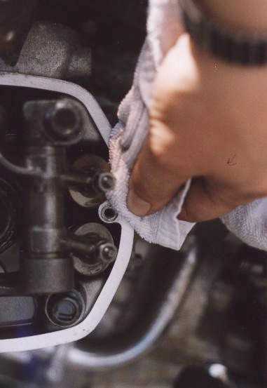
Don't drop anything down any of the
exposed works. If you have small children, keep them away. If you are disturbed
during the procedure, spread a rag or old towel over the exposed engine to stop
foreign object damage - maybe bird droppings - I've seen this happen.
Cylinder head bolts
- check
Whilst the cylinder heads are exposed,
you should check that the big 14mm head black bolts are correctly tightened.
Here are the settings. Check these before you adjust the tappets as if the head
bolts need tightening, this affects the valve clearances.
| All 500cc except
GL inc Turbo |
36 - 40 lb
/ ft
|
5 - 5.6 kg
/ m
|
| All 650cc and GL500 |
36 - 43 lb
/ ft
|
5 - 6 kg /
m
|
UNDER NO CIRCUMSTANCES DO THIS
"BY FEEL" as a stripped thread will mean removing the cylinder
head and having expensive and time consuming repairs done. Always use your
torque wrench.
Onwards ...
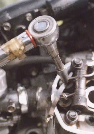
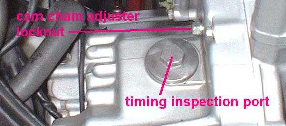 Photo
shows the rear right crankcase, the timing inspection port with the 17mm round
cover, and the manually adjusted cam chain tensioner locknut.
Photo
shows the rear right crankcase, the timing inspection port with the 17mm round
cover, and the manually adjusted cam chain tensioner locknut.
Thanks to Neil Babcock
for the very clear photo.
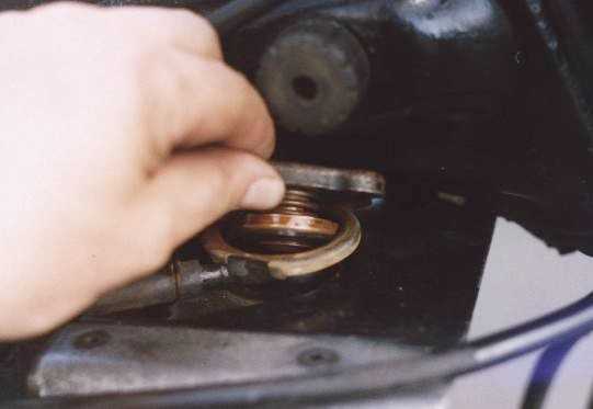
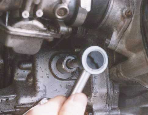 If
you have a manual cam chain tensioner, you will see a 10mm head bolt protruding
from the rear of thecrankcase, and just below this, a 17mm head round inspection
port cover.
If
you have a manual cam chain tensioner, you will see a 10mm head bolt protruding
from the rear of thecrankcase, and just below this, a 17mm head round inspection
port cover.
Newer models have a rubber tube from
the port cover leading to the air cleaner box directly behind; if so, pull the
tube off first. You will probably need an adjustable wrench to remove the port
cover, as the nut size is about 23mm I think. The older models have the plain
17mm port like the photo opposite.
Remove the round cover, but do not
do anything yet with the tensioning bolt. If you can't see a tensioning bolt,
you have an automatic cam chain tensioner, and your task will be somewhat easier.
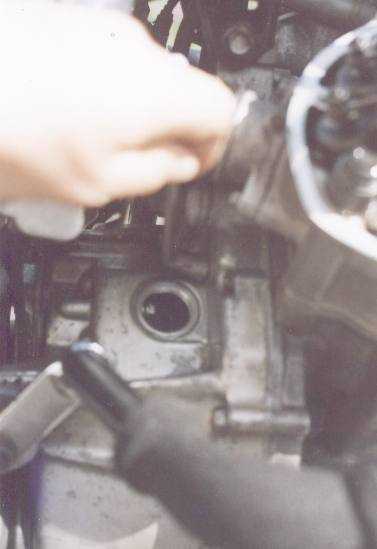
Wiggle the rear wheel and put the
gearbox into top gear (left).
 Sit
down close to the inspection port and peer into the crankcase aperture. If you
can't see in, a small lamp will help. You will see a circular flywheel with
a smaller dull metal circumference and a larger polished steel circumference.
Now reach back to the top of the rear tyre and firmly rotate the wheel clockwise
(or forward from the top). You will see the engine flywheel being turned "upwards".
Viewed from the front, this would be turning clockwise.
Sit
down close to the inspection port and peer into the crankcase aperture. If you
can't see in, a small lamp will help. You will see a circular flywheel with
a smaller dull metal circumference and a larger polished steel circumference.
Now reach back to the top of the rear tyre and firmly rotate the wheel clockwise
(or forward from the top). You will see the engine flywheel being turned "upwards".
Viewed from the front, this would be turning clockwise.
Your engine completes four strokes
for each complete cycle; intake with the piston descending and sucking in the
fuel / air mixture, compression with the piston ascending and squeezing the
mixture, combustion with the piston being driven down by the force of the explosion;
and exhaust with the piston ascending again and driving out the burned mixture.
Thus, at two stages in its cycle, the piston will be at its uppermost limit
of travel. This is called top dead centre, popularly called TDC.
The four stroke cycle is often called suck - squeeze - bang - blow.
|
Stroke
|
Inlet valves
|
Exhaust
Valves
|
Piston
is
|
|
Intake
|
Open
|
Closed
|
Descending
|
|
Compression
|
Closed
|
Closed
|
Ascending
|
|
Combustion
|
Closed
|
Closed
|
Descending
|
|
Exhaust
|
Closed
|
Open
|
Ascending
|
Valve clearances for each cylinder
are done with the engine set to TDC on the compression stroke, and the inlet
valves closed. The trouble is, the part of the crankshaft you can see will be
in exactly the same position at TDC for both the compression and the exhaust
stroke, and you can't tell by just looking at it which stroke it is on.
As you nudge the roadwheel clockwise,
watch the four exposed rocker arms on the RH cylinder head, right in front of
your nose. There are two pairs - inlet, nearest you; and exhaust, furthest away
from you. The nearest pair are the ones to watch, as when they have just finished
closing (rising up as you look at them) the engine is at TDC on the compression
stroke.
To get this exactly correct, gradually
nudge the road wheel clockwise and peer at the flywheel. Scored into it are
deep marks which tell you when the piston is at TDC. You will see first of all
a pair of unmarked lines come into view; then a mark with FR, then a
mark with TR.
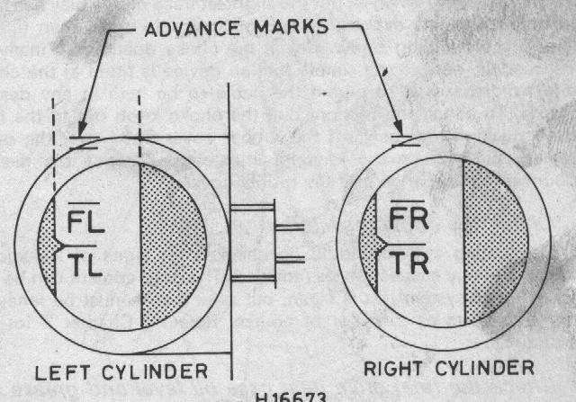 I
did photograph this view of the engine but it didn't come out, so here is a
drawing of what it looks like. Note that the calibration mark is the grey-shaded
pointer on the left of the aperture, and the FL/FR and TL/TR marks are on the
dull part of the flywheel.
I
did photograph this view of the engine but it didn't come out, so here is a
drawing of what it looks like. Note that the calibration mark is the grey-shaded
pointer on the left of the aperture, and the FL/FR and TL/TR marks are on the
dull part of the flywheel.
Ignore the FL and TL marks for the
moment.
Nudge the roadwheel forwards and
watch the inlet valves nearest you. When you see them rising, the piston is
coming up on the compression stroke; continue to nudge the roadwheel gently
until you see the TR mark align precisely with the calibration pointer.
If you are on the compression stroke, you will be able to rattle both the inlet
and exhaust rockers on the RH cylinder head.
 There
should be a small but feelable up-and-down movement, and an audible clack. If
you have the piston on TDC of the exhaust stroke, there is no free movement
of the inlet valves, they are locked up solid, and you need to turn the roadwheel
enough to nudge the engine round another complete turn to the TR mark again.
There
should be a small but feelable up-and-down movement, and an audible clack. If
you have the piston on TDC of the exhaust stroke, there is no free movement
of the inlet valves, they are locked up solid, and you need to turn the roadwheel
enough to nudge the engine round another complete turn to the TR mark again.
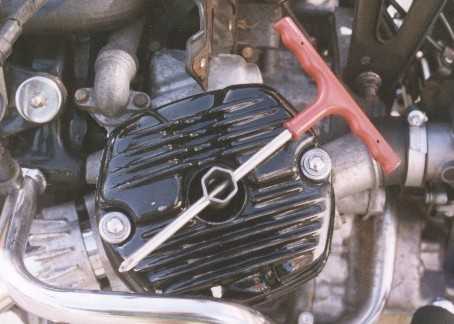
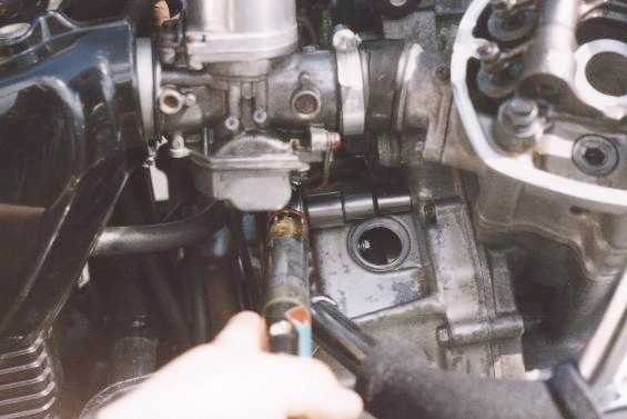
 One
good dodge here is to take a T-handled screwdriver and slide it into the hole
where the spark plug was. Whatever you do, don't use anything that could disappear
completely down the hole or you will have very major problems. A T-driver can't
fall right in. As you turn the engine, the T-driver is moved up and down by
the piston as it rises and falls, and it's consequently dead easy to see where
it is in its cycle of travel, as you can see it and feel it.
One
good dodge here is to take a T-handled screwdriver and slide it into the hole
where the spark plug was. Whatever you do, don't use anything that could disappear
completely down the hole or you will have very major problems. A T-driver can't
fall right in. As you turn the engine, the T-driver is moved up and down by
the piston as it rises and falls, and it's consequently dead easy to see where
it is in its cycle of travel, as you can see it and feel it.
Ok, you've got the RH cylinder at
TDC on the compression stroke. Setting the tappets or valve clearances means
checking and possibly adjusting the tiny amount of free space between the top
of the valves themselves, and the rocker arms (the mechanism which actuates
them). As the engine gets very hot and its metal expands, this clearance ensures
that the whole thing works correctly. It is measured in thousands of an inch
("thou") or tenths of a millimetre, and varies according to which
model of bike you have, as per the following chart.
Valve clearances (engine
cold)
| Model |
INLET
|
EXHAUST
|
| CX500Z,
A, B, C, all CX650 variants inc Turbo |
0.1 mm / 0.004"
/ 4 thou
|
0.12 mm /
0.005" / 5 thou
|
| All other 500cc
variants (Eurosport, GL500) inc Turbo |
0.08 mm /
0.003" / 3 thou
|
0.1 mm / 0.004"
/ 4 thou
|
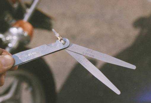 Your
feeler gauges are a set of slim steel tongues which are precisely machined to
a certain thickness, which is etched or stamped on them. For my bike's inlet
clearances, I will be using the gauge which has the thickness of 4/1000ths of
an inch, or "4 thou" or 0.004". If you work in millimetres, the
gauge is marked 0.1mm, i.e. 1/10th of a millimetre. For the exhaust clearances,
I will be using the gauge of 5/1000ths, "5 thou", 0.005", or
0.12mm. Your bike may be different - check with the above chart. Even if the
clearances are different, the technique of checking and adjusting is exactly
the same.
Your
feeler gauges are a set of slim steel tongues which are precisely machined to
a certain thickness, which is etched or stamped on them. For my bike's inlet
clearances, I will be using the gauge which has the thickness of 4/1000ths of
an inch, or "4 thou" or 0.004". If you work in millimetres, the
gauge is marked 0.1mm, i.e. 1/10th of a millimetre. For the exhaust clearances,
I will be using the gauge of 5/1000ths, "5 thou", 0.005", or
0.12mm. Your bike may be different - check with the above chart. Even if the
clearances are different, the technique of checking and adjusting is exactly
the same.
Some feeler gauges do not have a
single tongue for the required thickness. It's fine to slide two or more tongues
together to build up to the necessary thickness. For example, if you don't have
a 5 thou gauge, you can use a 3 thou and a 2 thou slid
together to add up to 5 thou. This is quite ok, but be
careful that no other gauges have accidentally slipped in between the ones you
want.
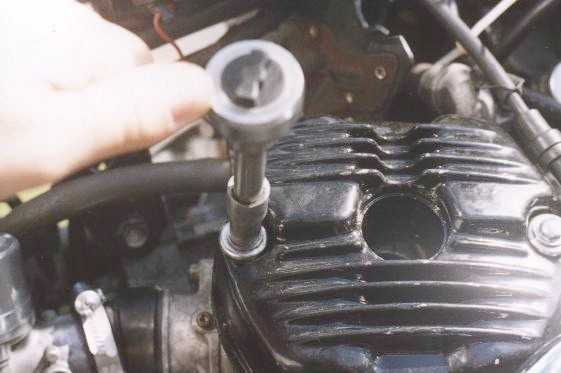
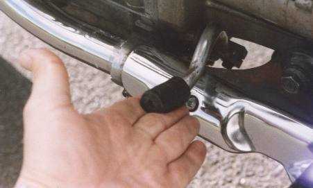
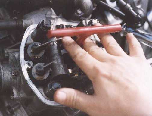
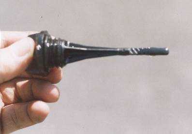
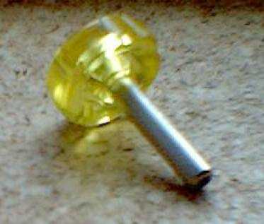 I've
now bought the special Honda tool for adjusting CX tappet screws - it's pictured
here and is part no 07708-0030400. If your dealer can't find this
part, try the alternative part number 07908-KE90200.
I've
now bought the special Honda tool for adjusting CX tappet screws - it's pictured
here and is part no 07708-0030400. If your dealer can't find this
part, try the alternative part number 07908-KE90200.
It's a handy mushroom-shaped tool
with a knurled handle, 1½" tall and with the exact size square hole
for getting those clearances spot on. Recommended, and only about £3.
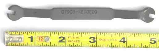 Dave
Harwood tells me of this alternative tool. He says "I think it's overpriced
at US$20 but it is longer and gives fine adjustments."
Dave
Harwood tells me of this alternative tool. He says "I think it's overpriced
at US$20 but it is longer and gives fine adjustments."
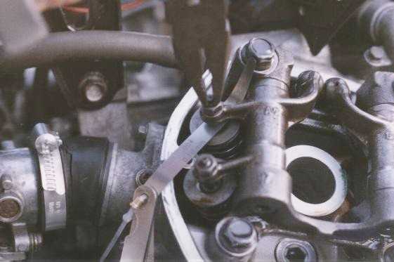 Slide
the gauge between the top of the valve stem and the bottom of the adjuster on
the rocker arm. It should be a close, snug fit, but should just be able to slide
in and out. If it won't go in at all, or rattles about too freely, the clearance
needs adjusting. Leave the feeler gauge in place, and use a 10mm ring spanner
to slacken the locking nut and a pair of slim nosed pliers to grip and turn
the adjusting screw gently.
Slide
the gauge between the top of the valve stem and the bottom of the adjuster on
the rocker arm. It should be a close, snug fit, but should just be able to slide
in and out. If it won't go in at all, or rattles about too freely, the clearance
needs adjusting. Leave the feeler gauge in place, and use a 10mm ring spanner
to slacken the locking nut and a pair of slim nosed pliers to grip and turn
the adjusting screw gently.
Useful Tip! After much experience
with this class of engine, I have found that the tappets will start to rattle
somewhere about the 1,000 mile mark after adjustment. This is an annoying thing
to happen, and now I set the clearances to very tight - so I can just
withdraw (drag!) the feeler gauge out afterwards.
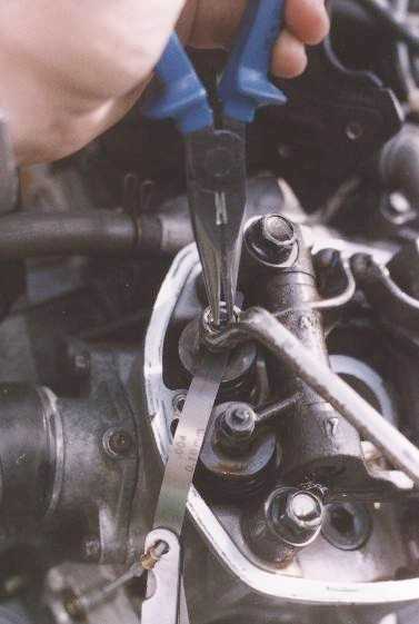
 Tweak
the adjusting screw whilst you slide the feeler gauge in the free space, until
the gauge can only just move, but is not trapped so tight that you can't extract
it. Now whilst you use pliers to hold the adjuster still, tighten the locknut
a little more than finger tight. Remove the ring spanner.
Tweak
the adjusting screw whilst you slide the feeler gauge in the free space, until
the gauge can only just move, but is not trapped so tight that you can't extract
it. Now whilst you use pliers to hold the adjuster still, tighten the locknut
a little more than finger tight. Remove the ring spanner.
Now check the clearance again. If
it's still ok, use your torque wrench to tighten the locking nut to the correct
setting of 11 - 13 ft lbs (500cc engines) or 14 - 18 ft lbs (650cc engines).
Check the clearance again, and readjust if necessary. Don't forget to use the
torque wrench to finally tighten the locknut.
(A rather unusual thing happened
when I did the tappets on 15-Apr-03. Two of the adjusting screws, on the same
cylinder head, stripped, despite using the correct torque. Luckily I had spares.
I now recommend not tightening them more than just above the lowest setting.)
This is all a little fiddly, and
sometimes you will wish that you had three hands - one to hold the feeler gauges,
one to hold the pliers and one to hold the spanner! But it ensures that your
valve clearances are spot on, and this staves off the dreaded tappet rattle
for longer than usual. It's all mostly a question of practice.
Repeat, checking the clearance on
the other inlet valve.
Now select the other feeler gauge
and check / adjust the slightly wider exhaust valves. These have different settings
because they have very hot exhaust gases rushing past them, whereas the inlet
valves are cooled by incoming unburned fuel / air mixture, and consequently
they don't get so hot.
That's dealt with the RH cylinder
and the LH one now needs the same procedure. Go back to the inspection port,
and this time nudge the rear wheel backwards, from the top of the tyre
(as if you were reversing the bike) as you peer in through the hole. When the
TL line (not the FL line) is against the calibration mark, the
left piston is as TDC. Check that the LH tappet arms are free and "clackable".
If you find they are locked up, nudge the engine round 360 degrees until the
TL mark comes up again, and recheck for free movement of the valve mechanism.
Check and adjust the clearances in just the same way as for the RH cylinder
head, remembering that the inlet and exhaust clearances are different.
When adjusting the left hand valve
clearances, the action of tightening the locknuts does tend to loosen the adjusting
screws very slightly. To avoid this, screw in the adjusters so that the feeler
gauges are just about slideable through the gap. Then check them after torqueing
the locknuts.
Don't turn the rear wheel or engine
just yet.
 If
you have a manual cam chain adjuster, use a 10mm ring spanner to undo the locknut
2 turns. Just in case the adjusting arm has stuck, give the tensioning bolt
a couple of firm taps (not a hefty great clout) and then set your torque
wrench to 6½ ft lbs and tighten the bolt. NEVER do this "by hand"
as if you strip the thread on the tensioning bolt, this is an engine-out job
to repair.
If
you have a manual cam chain adjuster, use a 10mm ring spanner to undo the locknut
2 turns. Just in case the adjusting arm has stuck, give the tensioning bolt
a couple of firm taps (not a hefty great clout) and then set your torque
wrench to 6½ ft lbs and tighten the bolt. NEVER do this "by hand"
as if you strip the thread on the tensioning bolt, this is an engine-out job
to repair.
Replace the inspection port cover,
finger tight plus 1/16 of a turn.
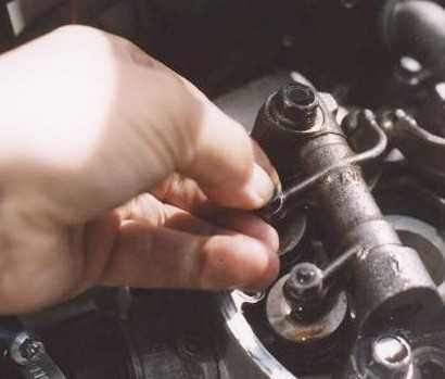
 Insert
one of the sparking plugs into the special spanner you used to extract it, and
examine it. The colour
of the plug gives a good indication of whether or not the fuel / air mixture
is correct. If the plug is a light or golden brown colour, this is fine. A sooty,
oily or obviously burned plug indicates a problem.
Insert
one of the sparking plugs into the special spanner you used to extract it, and
examine it. The colour
of the plug gives a good indication of whether or not the fuel / air mixture
is correct. If the plug is a light or golden brown colour, this is fine. A sooty,
oily or obviously burned plug indicates a problem.
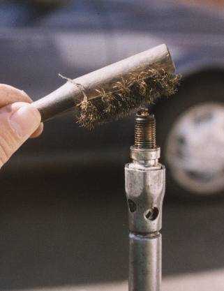
If you are not fitting new plugs,
give each old one a good going over with your wire brush and use your feeler
gauges to set the plug gap (between the central core and the little arm that
projects over it) as per the following chart. In fact always check the gap on
new plugs - they probably aren't correct. If the gap needs adjusting, gently
bend the outer curved-over electrode.
Now clean and gap-check the old plugs,
and put them in the boxes your new ones came in. Then put the boxes in your
travelling toolkit. Who knows when you may need a spare plug?
Sparking Plug Gap / Type
| Model |
Spark Plug
Type and Gap
|
| UK all 500cc variants
except Turbo |
NGK
DR8ES-L or ND X24ESR-U set to 0.6-0.7mm / 0.024 - 0.028" /
24 - 28 thou
|
| US all 500cc variants
(carbs with accelerator pump) |
NGK
D8EA or ND X24ES-U set to 0.6-0.7mm / 0.024 - 0.028" / 24
- 28 thou
|
| All 650cc variants
except Turbo |
NGK
DPR8EA-9 or ND X24EPR-U9 set to 0.8 - 0.9 mm / 0.032 - 0.035"
/ 32 - 35 thou
|
Check that the drain holes at the
bottom of the spark plug recesses are not blocked, then replace the spark plugs
in the cylinder heads; finger tight plus 1/8 of a turn with the spanner. To
eliminate the threat of cross threading a spark plug, push a 6" length
of flexible garden hose or aquarium pipe over the top of the spark plug ceramic
body and use that to twiddle the plug into place. If the thread tries to go
in cross threaded, the garden hose will slip free before any damage occurs.
This is especially useful on cylinder heads where the angle of the plug is such
that you can't see what you are doing, or where your fingers or plug box spanner
can't get square-on to the head.
 Check
that the two (inner and outer) cylinder head cover black rubber gaskets are
not damaged; ensure no debris or tools are left in the head spaces, clean the
mating surfaces and refit the covers, tightening the chromed bolts to no more
than 6½ ft / lbs. If the threads strip out - a common wear problem as
the bike ages - see this
page for how to repair them.
Check
that the two (inner and outer) cylinder head cover black rubber gaskets are
not damaged; ensure no debris or tools are left in the head spaces, clean the
mating surfaces and refit the covers, tightening the chromed bolts to no more
than 6½ ft / lbs. If the threads strip out - a common wear problem as
the bike ages - see this
page for how to repair them.
UNDER NO CIRCUMSTANCES TIGHTEN
THE 10mm CHROMED HOLDING BOLTS "BY FEEL" as the threads are
very easily stripped. Always use your torque wrench. In fact, these bolts
don't need to be very tight. Little more than finger-tight is quite enough.
By "finger tight" I mean
placing a 10mm socket on the top of the chrome nuts and turning the socket by
hand as far as you can comfortably do so. If afterwards you get an oil weep,
you can tighten them down a touch more than finger-tight. But these important
threads get a lot of wear with the necessity to check the tappets so often on
the CX engine and anything which reduces the danger to them is a good idea.
At least repairing them is
a simple task provided you have the correct threading kit, and isn't an engine-out
job.
The left and right head covers are
interchangeable, but they only fit one way up, as there is a moulded valley
for the spark plug leads, which you now snap back on.
 Before
you replace the fuel tank, remove the radiator cap and if necessary top-up the
coolant level with antifreeze or deionised water. When refilling or topping-up
the radiator, use a 50/50 mixture of distilled or deionised water (battery water)
and silicate-free antifreeze, with its distinctive orange or pink
colour. Silicate-free antifreeze is much better for the ceramic seal inside
the water pump, and cooling system generally.
Before
you replace the fuel tank, remove the radiator cap and if necessary top-up the
coolant level with antifreeze or deionised water. When refilling or topping-up
the radiator, use a 50/50 mixture of distilled or deionised water (battery water)
and silicate-free antifreeze, with its distinctive orange or pink
colour. Silicate-free antifreeze is much better for the ceramic seal inside
the water pump, and cooling system generally.
UK readers note that if you buy antifreeze
from Halfords, it should be the more expensive "Advanced" formula,
which does actually say silicate-free on the rear of the bottle.
Refit the cap and replace the fuel
tank; connect the fuel pipe(s). Turn on the fuel, checking for leaks.
Put the gearbox back into neutral
and start the engine in the usual way. A good method of identifying the source
of any noises is to place a small socket, on an extension bar, against various
places on the engine casings, and rest the other end of the bar just inside
your ear. You'll hear every sound. Experience is the best guide, but regular
whirrings are ok, anything heavily scraping, knocking or hammering needs investigation.
A child's play-doctor stethoscope is equally as good for listening to engine
noises.
 Short
road test and leaks check, and you're done. To check the oil level, remove the
dipstick, wipe it clean and reinsert it without screwing it in.
Remove it again and the level should be between the lower and higher marks,
anywhere in the criss-cross hatched area of the dipstick is fine. Top-up oil
if necessary but do not exceed the higher of the two levels.
Short
road test and leaks check, and you're done. To check the oil level, remove the
dipstick, wipe it clean and reinsert it without screwing it in.
Remove it again and the level should be between the lower and higher marks,
anywhere in the criss-cross hatched area of the dipstick is fine. Top-up oil
if necessary but do not exceed the higher of the two levels.
If you get an oil weep or minor oil
leak from where the rocker box cover meets the cylinder head, or from the water
drain hole half way down the outer face of the cylinder head, it is most likely
to be a misplaced rubber gasket, probably the centre "ring" one. Stop
the engine and remove the cylinder head cover. You can of course replace both
the black rubber gaskets, but a temporary fix is to use non-permanent gasket
sealing compound such as Hylomar, smeared on the mating surfaces. A leak here
will send oil all over your upper boot and shins, as well as dropping hot oil
on the exhaust collector box.
You are welcome to comment
on these pages.