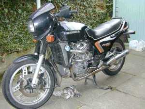
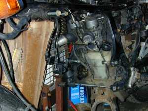
 This
UK CX500E-C "Eurosport" has a bad noise coming from the starter motor
area.
This
UK CX500E-C "Eurosport" has a bad noise coming from the starter motor
area.CX / GL 500 / 650 Engine removal
Words : Rob Davis. Pictures : Ian Shearer
The Honda CX / GL engine is quite a lump to work with. Whilst a strong person could lift it, manipulating it in and out of the frame is a job for two people. It is a potentially dangerous job if not approached carefully. Two people and a jack of some sort would be the minimum requirements.
The engine complete with radiator and starter motor weighs 155 lbs or about 60 kilos.
Skill / Time Levels
Skill : 3a. Personally dirty : 3. Work mess : 3. Space : 3.
Tools : 17mm, 14mm, 12mm, 10mm, 8mm socket and ring spanners; torque wrench; socket ratchet handle and extension bar; trolley, scissor or bottle jack; pliers; drain trays. All nut and bolt sizes are given for the spanner size required to fit them.
Skill levels explained.
(Americans call a "spanner" a "wrench". A ring spanner is a "closed end wrench".)
Time : expert 45 minutes, average 60 - 90 minutes, "first time" 90 - 120 minutes. The world record for an engine swap is 28 minutes!
I am very receptive to comments and suggestions, but you use these pages entirely at your own risk.
This
UK CX500E-C "Eurosport" has a bad noise coming from the starter motor
area.
Remember that Eurosports have subtly different frames to As and Bs. Don't panic if the pictures don't exactly match up with your variant of CX or GL.
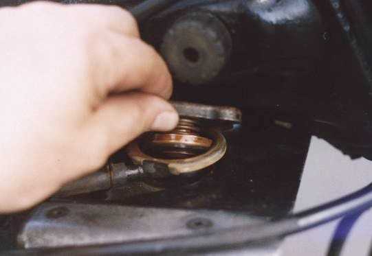
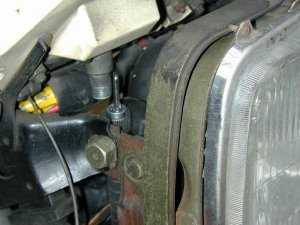
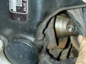
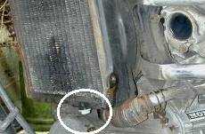 Drain
the coolant by removing the radiator cap (left) and then unscrewing the
12mm nut under the front left hand side of the radiator (right, ringed)
. This is a soft plastic nut and easily damaged.
Drain
the coolant by removing the radiator cap (left) and then unscrewing the
12mm nut under the front left hand side of the radiator (right, ringed)
. This is a soft plastic nut and easily damaged.
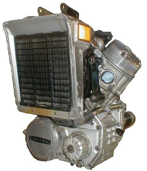
Although Ian removed his radiator in the pictures shown here, it's easier to work with it in place, and remove it with the engine as one complete lump. You don't need to detach the radiator unless you plan to :-
> work on the radiator, or change it;
> remove the front engine cover (ie get at the oil pump or chain)
> do serious engine internal work.
You can service or replace the clutch without removing either the engine or the radiator.
Pull off the long spark plug caps.
Disconnect the clutch cable at the engine end.
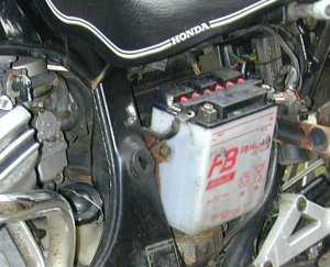 Remove
both side panels. They are quite useful places to store any odd bits - nuts,
bolts and so on. Unfasten the metal battery retaining strap and disconnect the
battery from the negative (black) and the positive (red) strap. Now remove the
battery and store it safely, where its contents can't be spilled.
Remove
both side panels. They are quite useful places to store any odd bits - nuts,
bolts and so on. Unfasten the metal battery retaining strap and disconnect the
battery from the negative (black) and the positive (red) strap. Now remove the
battery and store it safely, where its contents can't be spilled.
This gives you more space and prevents accidental electrical damage.
Whilst you have it out, give it a clean, and check the electolyte level.
You don't have to remove the carburettors. In this example, Ian didn't, but it does give you more manoeuvring space if they are taken out. If you don't remove the carburettors, unfasten the inlet tracts between the carbs and the cylinder heads. Each is held on with 2 x 8mm bolts. Don't lose the O-rings inside.
Really it's easier to work with the carburettors removed.
 Remove
the seat. On the Eurosport it's held on by the 2 bolts visible at the bottom
of the picture; on As and Bs there are 2 spring loaded catches under the seat.
Remove
the seat. On the Eurosport it's held on by the 2 bolts visible at the bottom
of the picture; on As and Bs there are 2 spring loaded catches under the seat.
Then disconnect the fuel pipes to the petrol tank. Vacuum-fed petrol taps have 2 pipes; other variants have one. The tank is retained by a single bolt at the rear, although some variants have two bolts at the front. Remove the tank and store it away from your working area, where it can't be damaged or start a fire. Don't store the tank at your only means of exit from a working area.
It's a good idea to replace nuts, bolts and washers where they came from, so you don't lose track of what goes back where.
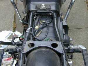
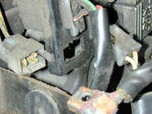
 If
your bike has a fuel gauge, disconnect it. Here it's shown in the centre of
picture. Disconnect the oil pressure lead (blue and red) and the low tension
ignition lead (black with a white streak).
If
your bike has a fuel gauge, disconnect it. Here it's shown in the centre of
picture. Disconnect the oil pressure lead (blue and red) and the low tension
ignition lead (black with a white streak).
 The
side panels, battery, saddle and tank removed.
The
side panels, battery, saddle and tank removed.
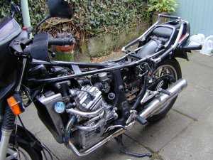
 The
bike in this example has a Motad 2:1 one-piece exhaust fitted, which unbolted
as a single unit.
The
bike in this example has a Motad 2:1 one-piece exhaust fitted, which unbolted
as a single unit.
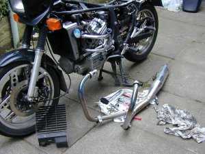
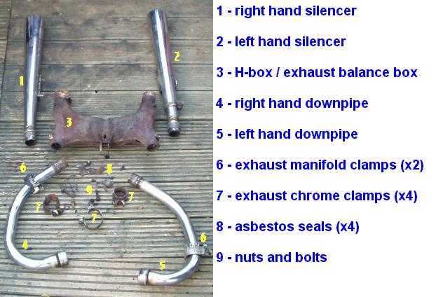
If your bike has a standard 2:2 exhaust fitted, undo the 2 x 10mm nuts retaining the exhaust header pipe on the LH cylinder head. Undo the 12mm head clamp holding the header pipe to the H-box (collector box) underneath the engine and work the header pipe free. When loosened, it just clears the stubs at the exhaust port. Recover the copper crush gasket from inside the exhaust port.
Undo the 12mm head clamp holding the LH silencer to the H-box. Undo the 14mm bolt holding the LH silencer to the pillion footrest bracket and pull off the silencer.
Repeat with the RH exhaust system. Give the entire system a thorough clean and polish whilst it's disassembled, especially on the inside faces of the silencers, where the ribbed chrome tends to collect muck and rust.
Unbolt the H-box from its mounting points under the engine, and remove it. This is a good time to give it some fresh heatproof paint, or at least brush it free of rust and dirt. It looks good when sprayed with black gloss heatproof paint!
Here is an "exploded" photo of the standard exhaust components. The various types of 500 and 650 don't vary much, and what differences exist, are mainly cosmetic.
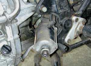 Undo
the heavy duty cable to the starter motor. You may optionally remove the starter
motor - held on by two bolts going inwards to the engine, directly behind the
starter motor body. Then pull the starter motor backwards to remove it. You
may find it easier to remove the gear change lever first - it's held on from
underneath with a 10mm pinch bolt.
Undo
the heavy duty cable to the starter motor. You may optionally remove the starter
motor - held on by two bolts going inwards to the engine, directly behind the
starter motor body. Then pull the starter motor backwards to remove it. You
may find it easier to remove the gear change lever first - it's held on from
underneath with a 10mm pinch bolt.
 Inside
the headlight nacelle, disconnect the rev counter (tachometer) cable. As you
look at the assembly from the front, the tachometer is the left hand side drive
cable.
Inside
the headlight nacelle, disconnect the rev counter (tachometer) cable. As you
look at the assembly from the front, the tachometer is the left hand side drive
cable.
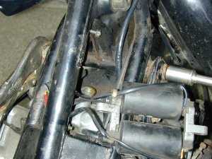
 Fold
back the ribbed rubber boot at the RH lower rear of the engine, where the shaft
drive disappears into the front of the swinging arm. Remove the pinch bolt on
the drive shaft and push the heavy steel shaft drive backwards, to disengage
it from the engine. Don't worry, you can't lose it.
Fold
back the ribbed rubber boot at the RH lower rear of the engine, where the shaft
drive disappears into the front of the swinging arm. Remove the pinch bolt on
the drive shaft and push the heavy steel shaft drive backwards, to disengage
it from the engine. Don't worry, you can't lose it.
650s don't have the pinch bolt, but are otherwise the same.
At the rear of the engine you will also find the neutral switch lead running upwards over the alternator area. Trace this to the wiring harness, and disconnect it.
Disconnect the water bottle from its feed pipe. There will probably be a slight coolant spill.
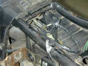
 Disconnect
all undersaddle connector blocks leading from the alternator (rearmost lower
part of the engine) to the various other electrical components; battery, CDI
or Transistorised Ignition boxes. Thoroughly clean all the male and female connections.
Disconnect
all undersaddle connector blocks leading from the alternator (rearmost lower
part of the engine) to the various other electrical components; battery, CDI
or Transistorised Ignition boxes. Thoroughly clean all the male and female connections.
Route the heavy cables from the alternator free of the frame so that as the engine is lowered, the cables are not pulled or damaged.
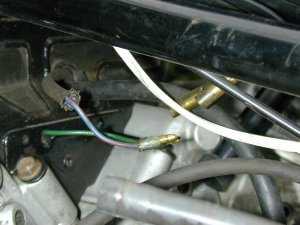 Disconnect
the temperature gauge sender connector cable (right) at the top of the
engine.
Disconnect
the temperature gauge sender connector cable (right) at the top of the
engine.
If you wish to remove the coils for improved access, trace their thin yellow and red leads from the coils back to the undersaddle area, and disconnect them. Unbolt the coils and store them out of the way.
 At
the top front of the engine (close to where the main spar meets the headstock)
are the engine-to-frame retaining bolts.
At
the top front of the engine (close to where the main spar meets the headstock)
are the engine-to-frame retaining bolts.
Attach a ring spanner to the nut and a socket spanner to the bolt, and remove the nut. Don't withdraw the bolt yet.
Repeat with any other heavy mounting bolts. CX500As and Bs have three of them in a triangle shape, base upwards.
Here a Mole self locking wrench has been used to hold the nut, presumably because it's been chewed up by a previous spannerman. If you find nuts like this, replace them.
Remove the two short bolts holding the rear engine casing to the frame (directly under the carb space). Remove the nut on the end of the long engine bolt which passes right underneath the rear of the engine, but don't pull the bolt out yet.
The Z (original CX500), A and B models have two triangular shaped engine-to-frame mounting plates which are located at the top of the engine, just forward of the carburettors. You can see these on this page. Unbolt the plates and remove them.
Disconnect the black water pipe from the top of the impeller pump at the rear of the engine.
Caution!
Before using your jack to lower the engine, have a good look round its circumference to check that all connections and leads are free.
A useful accessory here is a 12" square block of chipboard or a short plank, to help the engine balance on the jack. Raise the jack until it has taken the full weight of the engine and now withdraw the engine mounting bolts which you previously loosened off.
Martin Groen, from Holland,
comments "The 650, unlike the 500, has a lowered oil reservoir.
If, while loosening the engine you need to support the engine in this lowered
part only, it won't be stable. I used some extra wood to support both the reservoir
and the bottom of the rear cover for proper balance."
 Lower the engine SLOWLY checking for anything still attached, it's easy to overlook
a small connector, or to have some electrical cabling or piping trapped.
Lower the engine SLOWLY checking for anything still attached, it's easy to overlook
a small connector, or to have some electrical cabling or piping trapped.
The engine, without radiator and starter motor, weighs 140lbs and is very top heavy and unstable. It needs 2 people, one to steady the engine, one to operate the jack.
 If
everything is clear, lower the jack fully. You may find it useful to bear down
on the rear part of the bike, to raise the front, as you move the engine completely
clear of the frame.
If
everything is clear, lower the jack fully. You may find it useful to bear down
on the rear part of the bike, to raise the front, as you move the engine completely
clear of the frame.
Withdraw the engine to the left, as then the rear brake lever doesn't get in the way.
 Bob
Kingsmill made up a trolley jack system which made it very easy (right)
to manipulate the engine of his GL500.
Bob
Kingsmill made up a trolley jack system which made it very easy (right)
to manipulate the engine of his GL500.
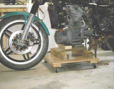
 Sture
(in Denmark) made up a handy trolley (left) with an adjustable height platform.
Sture
(in Denmark) made up a handy trolley (left) with an adjustable height platform.
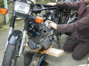
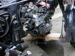
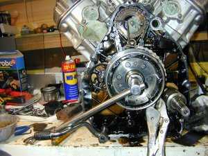
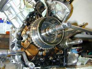
 One
2 man lift later, and the engine is on the bench. Strong and burly types can
lift it without help, but it's a struggle. I was just able to lift it into and
out of a car boot, but I don't think I could lift it onto a workbench.
One
2 man lift later, and the engine is on the bench. Strong and burly types can
lift it without help, but it's a struggle. I was just able to lift it into and
out of a car boot, but I don't think I could lift it onto a workbench.
If you must lift it on your own, stand astride it with your knees bent and lift using the power of your legs, keeping your back straight. Don't bend over the engine to lift it, you can damage your back doing it this way.
You can get it into the boot of a car by using a wooden ramp to drag the engine high enough to clear the lip of the car's boot area. Prepare the car boot with plastic sheeting and old towels, as oil and coolant will leak out from the CX engine. Lay it on its front end and pack it with old towels or boxes, to stop it rolling about as you drive the car.
Refitting the engine
Clean the engine casings as thoroughly as possible. Solvol Autosol is not the ideal cleansing agent; asking around other CX owners showed that the favoured method was an electric Dremel hand tool, with graded polishing wheels plus loads of time and elbow grease. Heatproof engine lacquer looks quite outstanding when applied to a freshly polished engine.
Generally, replacing the engine is a straightforward reversal of removal. It CAN be done single handed but it's far easier with two people. Some tips may be useful:-
> The shaft drive sliding collar is particularly awkward to engage with the gearbox output shaft, as the rubber boot gets in the way and space here is very limited. Fold the boot right back over itself before reinstalling the engine. Ensure the steel ring is installed over the gearbox output shaft, as the front edge of the boot engages with this and if you forget it, you'll have to drop the engine again to put it on (don't ask me how I know).
> When raising the jack and offering up the engine to the frame, beware that wires and cables don't get snagged and damaged.
> Clean off and grease all the engine-to-frame bolts so next time they will come out easily. I also push some grease well into the bolt holes. All this helps to stop corrosion developing.
> Fit the topmost front engine-to-frame bolt first and set the nut finger-tight. Then raise the rear of the engine and fit the long lower bolt. Finally insert the remaining bolts. Don't torque down the nuts until everything is connected up, as you may need to jiggle the engine to pass a cable or wire past some obstruction. Torque settings for the engine-to-frame bolts are surprisingly high, and are on this page.
> Check that all the electrical gadgets work (especially neutral and oil pressure) before starting the engine.
> I know you're raring to go, but have a coffee break before that first attempt to start the engine. When you come back refreshed, check everything again. You may find you have overlooked something. A second opinion here does no harm at all.
> You can test fire the engine without the exhausts fitted, but it is unbelievably noisy (dreadful popping racket) and the flames from the exhaust manifolds are astonishingly long, be wary of fire or burns.
Additional pictures
 Eurosport
frame after engine removal. Carbs are still fitted.
Eurosport
frame after engine removal. Carbs are still fitted.
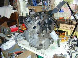
 Rear
of engine, before cleaning.
Rear
of engine, before cleaning.
 Rearmost
small cover removed, showing the ignition sensors for transistorised ignition.
Rearmost
small cover removed, showing the ignition sensors for transistorised ignition.
 Ian
says "This chrome water pipe bracket bolt did not want to come off, after
drilling the top off the allen bolt."
Ian
says "This chrome water pipe bracket bolt did not want to come off, after
drilling the top off the allen bolt."
 Ian
says "How not to do it. One must remember not to get carried away in the
heat of the moment..."
Ian
says "How not to do it. One must remember not to get carried away in the
heat of the moment..."
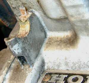
Broken water transfer pipe mounting bracket.
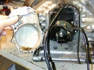
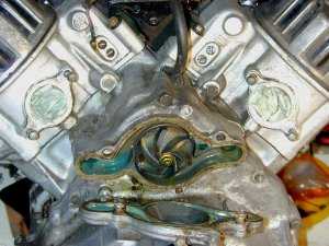 Water
pump cover coming off (Ian says "after a great deal of persuasion").
Water
pump cover coming off (Ian says "after a great deal of persuasion").
Note the newspaper stuffed into open inlet manifolds, to prevent FOD (foreign object damage).
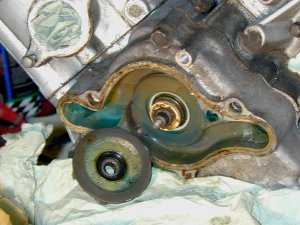 Water
pump impeller removed.
Water
pump impeller removed.
 Ian
says "More persuasion later, the rear cover finally frees up (right).
Remember, it has all been together for 18 years!"
Ian
says "More persuasion later, the rear cover finally frees up (right).
Remember, it has all been together for 18 years!"
Stubborn rear engine casing bolts may need an impact driver to remove. I recommend replacing the standard Honda bolts with Allen screws.
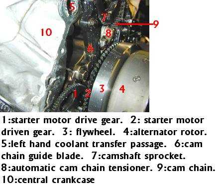 Inside
the rear casing. Here you can see the reason for the engine noise - the cam
chain guide blade (6) is cracked.
Inside
the rear casing. Here you can see the reason for the engine noise - the cam
chain guide blade (6) is cracked.
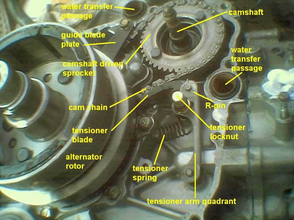
Below is another view of the alternator rotor and cam tensioner apparatus from a CX500A. Note that this is the manual tensioner.
 Loosening
the alternator rotor retaining bolt. Ian says "Note my cunning device to
stop the rotor rotating, fashioned from a pair of vicegrips, chain from an oil
filter removal tool, and an allen key."
Loosening
the alternator rotor retaining bolt. Ian says "Note my cunning device to
stop the rotor rotating, fashioned from a pair of vicegrips, chain from an oil
filter removal tool, and an allen key."
I'd recommend the proper Honda tool myself! The thread is the same as the oil filter bolt, but don't use the actual bolt to remove the rotor, as the bolt isn't strong enough.
If you can't use the proper tool, don't use a chain strap (hard metal type) as this cvan damage the alternator rotor. Use a strap wrench (fabric webbing type) instead.
 If
at first you don't succeed ... trying to get the rotor off its taper using the
oil filter bolt - not recommended by Haynes, as it is not a solid bolt.
If
at first you don't succeed ... trying to get the rotor off its taper using the
oil filter bolt - not recommended by Haynes, as it is not a solid bolt.
When refitting the rear cover, don't tighten the bolts until the action of the gear lever is found to be correct. It's extremely easy to dislodge the gear level actuating teeth whilst easing the rear cover into place.
You certainly don't want to find that you can't select gears after you've replaced the engine in the frame ...
Some tips on refitting the engine
Brent in New Brunswick says "If the shaft drive rubber boot gets too much in the way whilst you replace the engine, try pulling it backwards using bungee straps, to hold it clear whilst you engage the drive shaft with the gearbox output shaft."
With the engine and a-frame (even the radiator, if you like) bolted up, jack the motor and push through the frontmost holding bolt just aft of the headstock. In effect this lets the engine pivot fore-and-aft, quite freely. Give the nut a couple of turns to ensure the bolt can't drop out and check the harness isn't trapped if the engine moves.
Be sure the rubber boot is over the front end of the swinging arm - and that the flange it fits onto is on the back of the engine case!
With a pal holding the engine for a few seconds, relocate the jack under the rear case and edge the engine up, feeding in the drive shaft collar as the engine is very gently raised. As it pivots on the singe front bolt, you can jiggle it quite a lot to help you marry up the shaft.
As soon as the shaft is engaged, pull the sliding collar forwards and pin it with the pinch bolt. Now raise the engine fully and wiggle it in between the rear bolt locations and then slip the long bolt through the underside, followed by the others. Do them finger tight as you may still need to wiggle things a bit more to get them all in.
I can see that having the gearbox in gear might well help as the two bits of the transmission shaft marry up. There's enough play in the shaft drive end to let you engage them.
This method gives you a lot more finger space in what is a tight spot. Once the motor is fully bolted in there is very little space to work.
 View
of the cam chain and tensioner
assembly after the alternator rotor has been removed, but before the tensioning
apparatus has been dismantled. This shows the cracked camchain guide blade (left
run of chain) and the cracked tensioner blade (right run of chain).
View
of the cam chain and tensioner
assembly after the alternator rotor has been removed, but before the tensioning
apparatus has been dismantled. This shows the cracked camchain guide blade (left
run of chain) and the cracked tensioner blade (right run of chain).
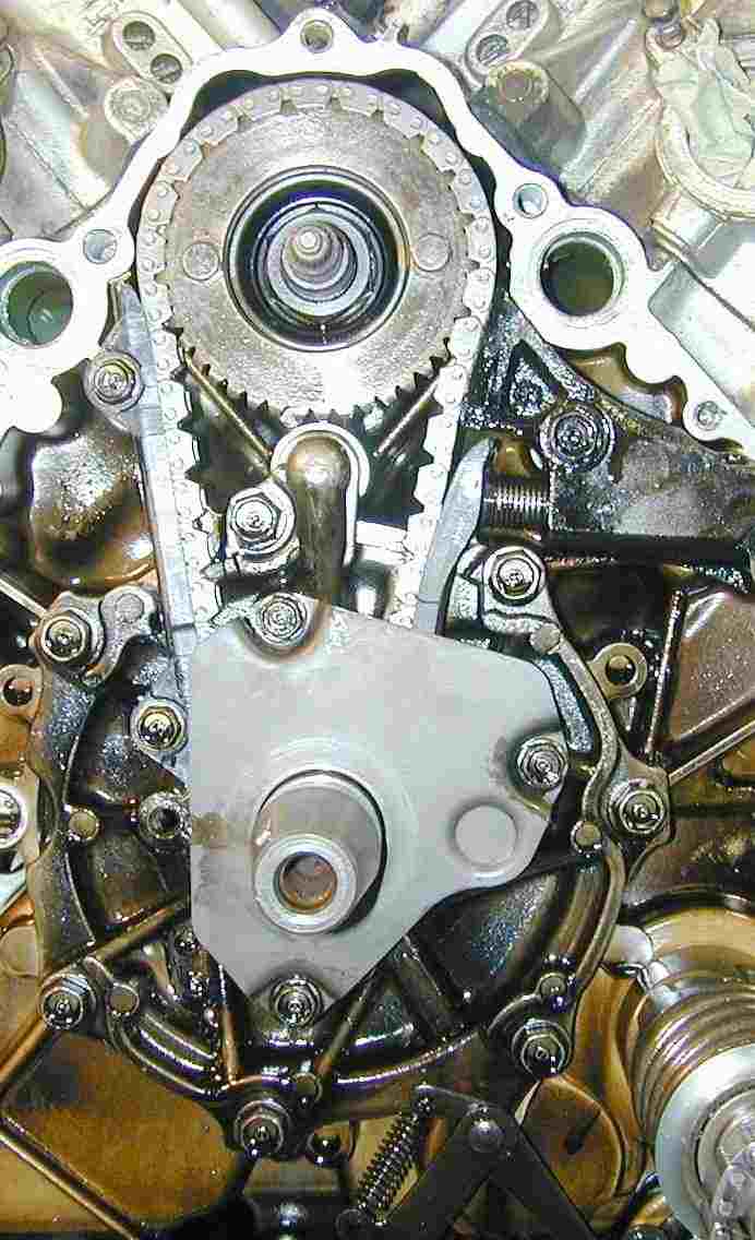
Note that this Eurosport model has the short tensioner plate; this is correct, as it has the automatic tensioner. Compare this to the modified type, with the extended upper plate, in the pictures above, for a Z, A, B, C and D models.
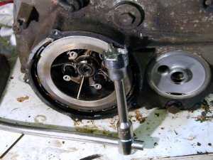 Special
tool to remove the clutch centre bolt,
made up from a socket trimmed down with a hacksaw. True home engineering, this!
Special
tool to remove the clutch centre bolt,
made up from a socket trimmed down with a hacksaw. True home engineering, this!
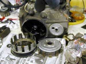 Clutch
out and dismantled.
Clutch
out and dismantled.
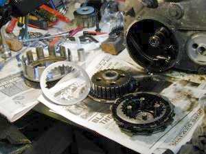 Sparkling-clean
clutch plate after the glaze has been removed.
Sparkling-clean
clutch plate after the glaze has been removed.
MANY THANKS indeed to Ian Shearer who spent a lot of extra time putting down the spanners, wiping his hands, and then taking the pictures. A sure way to make sure that the job took twice as long as it should have done.
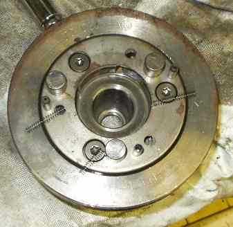 Maurice
McAllen sent this picture (right) of the starter motor clutch roller assembly.
Maurice
McAllen sent this picture (right) of the starter motor clutch roller assembly.
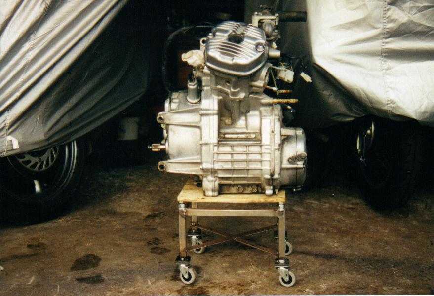
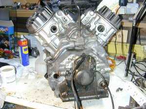
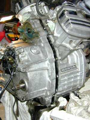
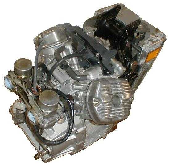
CX500 Z, A, B or C engine removed as a complete unit, complete with radiator, engine hanger and carburettors. Other variants have only minor visible differences.
You are welcome to comment on these pages.