CX/GL
500/650 Removing & Replacing the Water Pump & Mechanical Seal
The Yamaha
replacement mechanical water seal
The first section
of this page describes the problem, and the Yamaha alternative seal. The second
part covers how to change it and service the water pump / impeller.
NOTE
that the Yamaha mechanical seal should not be used with the 27mm rear casing
aperture (details further down).
HOWEVER
a recent experiment showed that the Yamaha seal DOES fit the 650.
 When
your CX or GL starts weeping ominous brown (seriously old antifreeze) , green
(the wrong kind of antifreeze) or pink (correct type of antifreeze) fluid, or
engine oil, from the water pump area onto the top of the alternator casing,
and then down the left hand side of the engine onto the H-box, you start to
worry about all sorts of things being wrong. This leak is almost always caused
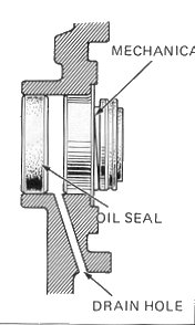
by a special seal, called the mechanical water pump seal, having failed. This
seal is located in the rear engine casing, behind the water pump impeller, and
it prevents oil lubrication from the camshaft area (which drives the water pump)
from mixing with the cooling fluid. When the seal starts to fail, it allows
cooling fluid to escape from a small overflow hole.
When
your CX or GL starts weeping ominous brown (seriously old antifreeze) , green
(the wrong kind of antifreeze) or pink (correct type of antifreeze) fluid, or
engine oil, from the water pump area onto the top of the alternator casing,
and then down the left hand side of the engine onto the H-box, you start to
worry about all sorts of things being wrong. This leak is almost always caused
by a special seal, called the mechanical water pump seal, having failed. This
seal is located in the rear engine casing, behind the water pump impeller, and
it prevents oil lubrication from the camshaft area (which drives the water pump)
from mixing with the cooling fluid. When the seal starts to fail, it allows
cooling fluid to escape from a small overflow hole.
However, if you
have coolant leaking in this area, it might be something as simple as failure
of the O-ring at the water pump end of the chrome water transfer pipe.
This is easy to diagnose. Run the engine and shine a lamp into the area, watching
carefully. If the mechanical seal is leaking, coolant comes out of a small drain
hole directly under the water pump casing. A failed O-ring causes drips directly
around and under the top end of the chrome pipe. If in doubt, stuff kitchen
roll all round the area and see which part is wet. If it's a failed O-ring,
remove the pipe (photos below) and change the O-ring. Read the part at the end
of this article about one problem associated with the reassembly.
The weep might
also be caused by a damaged or cracked coolant feed pipe. This is a
slender rubber tube which runs across the top of the engine from the thermostat
to a stubby pipe on the top of the water pump housing, being secured with a
simple spring clip. The tip of the this hose at the water pump end can crumble
or degrade, or the nasty spring clip can just wear out. Some kitchen roll stuffed
around this area will easily show a leak - if this is the culprit, and there
is slack on the pipe, cut off the last 1/2 inch and secure the fresh end to
the stubby pipe with a proper Jubilee clip. Or, replace the pipe.
Another weep cause
can be that the dome nut which retains the water pump impeller has become detached.
This can be easily seen once the water pump cover is removed, and is fixed without
dropping the engine.
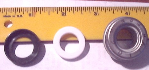
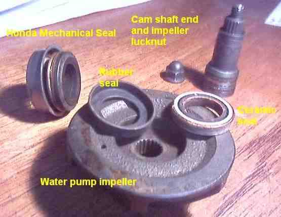 The
mechanical seal is in three parts (left). A rubber seal and base, which locates
into a recess in the rear (flat) face of the water pump impeller; a ceramic
seal like a large Polo Mint that abuts to it, and a shaped metal seal which
locates into the hole where the camshaft pokes through, and which is spring-loaded
against the ceramic washer. The ceramic washer turns with the water impeller
- but the spring loaded part doesn't. So, wear and eventually leakage between
these two components is inevitable.
The
mechanical seal is in three parts (left). A rubber seal and base, which locates
into a recess in the rear (flat) face of the water pump impeller; a ceramic
seal like a large Polo Mint that abuts to it, and a shaped metal seal which
locates into the hole where the camshaft pokes through, and which is spring-loaded
against the ceramic washer. The ceramic washer turns with the water impeller
- but the spring loaded part doesn't. So, wear and eventually leakage between
these two components is inevitable.
Note that the metal thrust washer
which fits between the flat face of the impeller and the camshaft is shown here
still in place on the end of the camshaft, just below the ribbing.
It is this weeping that causes the
wet leak. Fortunately, failure is usually slow, allowing plenty of time for
the problem to be addressed; and no harm is done unless the water loss is enough
to lower the level in the radiator. You can ride home provided that you keep
topping up the radiator, and you don't let the temperature gauge go over 80%,
or into the red. Remember that you should not remove a hot radiator cap without
a thick rag over it, as when the radiator pressure is relieved, the remaining
water boils instantly and squirts very powerfully out of the filler cap. You
can sustain serious scalds. If in doubt, wait until the engine has cooled.
So, is the solution a straightforward
fix? Well, yes and no.
No, because:-
(1) the mechanical seal is what's
called an interference fit in the crankcase.
An interference fit
means that the rear engine casing must be stripped bare and then heated to at
least 150C to expand it. This allows the seal to be very carefully driven in.
The actual seals are both ceramic and particularly fragile. Most of us wait
until the wife is out, and then put the degreased rear casing first in the dishwasher
and then in the domestic oven.
(2) whilst you can theoretically
get at, and change, the seal without removing the engine, in practice this is
so difficult (through lack of space) that the time lost in removing the engine
is easily won back again. Also, more importantly, leaving the engine in the
frame does not allow you to replace the inner oil seal, which should be changed
at the same time.
and
(3) a recent mechanical seal change
job went off the rails when we discovered that there are two subtly different
models of rear crankcase cover fitted to the CX and GL engines. Whilst some
crankcases have the 28.3mm aperture, some engines have the smaller 27.8mm size.
27.8mm or 28.3mm
mechanical seal aperture?
It has proved impossible to determine
which models have which sized aperture, due to the fact that so many bikes have
had entire engine or rear case transplants.
After a great deal of discussion
with fellow spannermen, I have to advise readers of this page not to use the
Yamaha seal with the 27mm aperture. Most attempts have failed, and if you have
the smaller aperture, the Yamaha seal being a mere 0.7mm more in diameter than
the Honda one, is just too big to be persuaded to fit.
The Yamaha seal is fine with the
28mm aperture and the Honda mechanical seal fits either size.
The Honda mechanical seal I bought
in May 2005, for a CX500A, measures 1.129" (28.66 mm) in diameter and its
Polo Mint was 0.905" (22.99mm) diameter, 0.156" (3.95mm) thick. Without
compressing the spring, the seal was 0.634" (16.11mm) deep. The inner diameter,
measure at the metal end which goes into the aperture, was 0.5635" (14.32mm).
The Yamaha "Polo Mint"
ceramic seal, which sits in the rear of the impeller, is 0.9035" (22.95
mm) in diameter, and is 0.156" (3.96 mm) thick.
It is suggested that you scribe "27mm"
or "28mm" on your rear casing, once you know the aperture size.
You have to remove the engine and
rear crankcase to do this job. But you don't need any special tools (you're
not forced to remove the alternator rotor). All the same, it's
an ideal time to pop off the alternator rotor and check the camchain tensioning
apparatus, alternator stator and water pump, whilst you are in there. Especially
if the cam chain and/or tensioner have done more than 20,000 miles - I strongly
recommend that you change the chain and tensioner blades, whether the manually
adjusted (all 500s except Eurosport) or automatic (late model GL500s, all 500
Eurosports and all 650s).
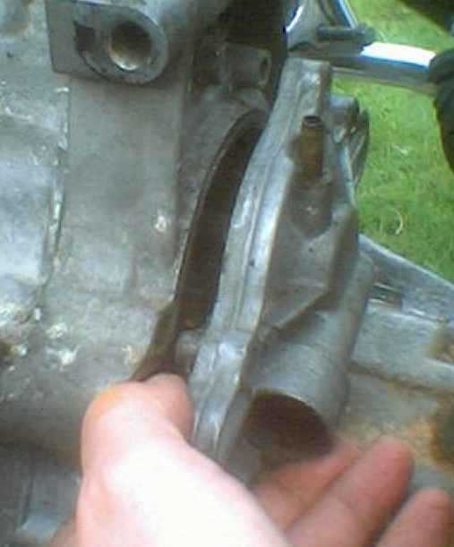
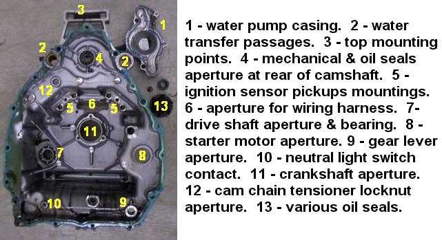
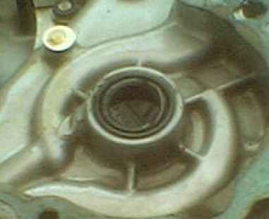
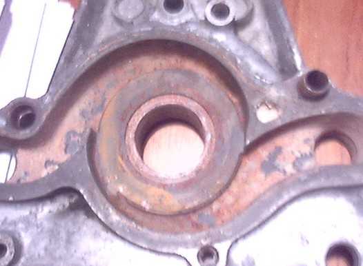 This
is the top part of the rear crankcase (left) after removal from the engine,
seen from the outside, and with the water pump impeller removed. The snake-like
passages are where the coolant is pumped out to the cylinder heads, and the
central hole is where the end of the camshaft sticks through. It is to the end
of the camshaft that the impeller is bolted, and between the two goes the mechanical
seal.
This
is the top part of the rear crankcase (left) after removal from the engine,
seen from the outside, and with the water pump impeller removed. The snake-like
passages are where the coolant is pumped out to the cylinder heads, and the
central hole is where the end of the camshaft sticks through. It is to the end
of the camshaft that the impeller is bolted, and between the two goes the mechanical
seal.
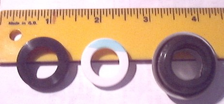 This
is the Yamaha mechanical seal, part number 11H-12438-10 (right)
in its three component parts. The ruler is in inches. From left to right, the
rubber base which sits in a recess in the rear (flat) face of the water pump;
the "Polo Mint" ceramic washer; and the mechanical seal body.
This
is the Yamaha mechanical seal, part number 11H-12438-10 (right)
in its three component parts. The ruler is in inches. From left to right, the
rubber base which sits in a recess in the rear (flat) face of the water pump;
the "Polo Mint" ceramic washer; and the mechanical seal body.
This view would be from the water
pump impeller end.
If you unthinkingly separate the
rubber base from the ceramic seal, note that the blue flash on the ceramic seal
faces outwards, towards the rear of the impeller and towards the rear wheel.
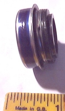
 The
same view (left) but the opposite sides of the items. Note the orientation of
the ceramic seal, with the blue flash not visible.
The
same view (left) but the opposite sides of the items. Note the orientation of
the ceramic seal, with the blue flash not visible.
This view would be from the camshaft
end.
 Mechanical
seal - the face that locates against the ceramic seal which sits on the flat
face of the water impeller. From this angle you can't see the spring loaded
part of the seal.
Mechanical
seal - the face that locates against the ceramic seal which sits on the flat
face of the water impeller. From this angle you can't see the spring loaded
part of the seal.
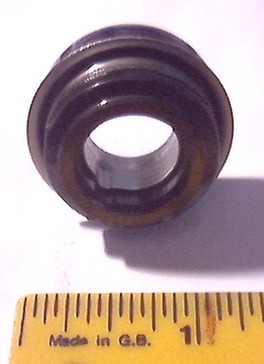
 The
mechanical seal edge-on. Here, you can see the spring loaded mechanism. The
blue band is a built-in sealing compound.
The
mechanical seal edge-on. Here, you can see the spring loaded mechanism. The
blue band is a built-in sealing compound.
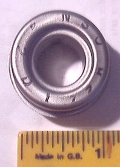 A
close-up of the mechanical seal's face which is pushed into the camshaft aperture,
towards the inside of the engine.
A
close-up of the mechanical seal's face which is pushed into the camshaft aperture,
towards the inside of the engine.
 The
mechanical seal placed, but not inserted, into the camshaft aperture.
The
mechanical seal placed, but not inserted, into the camshaft aperture.
Where can I buy
this Yamaha item?
Any Yamaha dealer! I bought my two
seals mail-order from:-
Fowler's
Motorcycles, Retail Mail Order Dept., 2-12 Bath Road, Bristol, Avon
UK BS4 3DR. 0117 977 0466. The total price for two seals including
postage and VAT was £21.97.
Part number 11H-12438-10.
David
Silver quotes £20 + postage and VAT (approx £23) for the
genuine Honda mechanical seal.
Servicing the water
pump, impeller, and changing the mechanical seal
Skill
Levels explained.
Skill Level : 3a.
Personally dirty : 3a. Work mess : 3a. Tools : 3a. Space : 2.
All nut
and bolt sizes are given for the spanner size required to fit them.
Engine out - or not?
If you have coolant weeping from
the drain hole under the water pump casing, there are two things you can try
before delving deeply inside the engine. Firstly, remove the water pump casing
and the impeller and simply replace the ceramic seal, its rubber boot, and thrust
washer, the brass washer and the dome nut. You will still have to buy a complete
mechanical seal etc but you can change these parts easily without
any major work, and without dropping the engine. Secondly, when
you reassemble the water pump, replace the O-rings in the water pump casing
and torque the impeller dome nut and the casing bolts to a little more than
the lowest setting. However if these ideas don't work, you will have to do a
full mechanical seal replacement.
If you have engine oil weeping out,
there is only one solution - drop the engine and change the oil and mechanical
seals.
Removing the old mechanical seal
is straightforward enough even without dropping the engine. I managed to get
the old seal out, but there was some minor damage to the lip of the casing where
the seal fits. The problem was simply that the seal, especially the Yamaha one,
is such a tight fit in the aperture that I'd say that it's next to impossible
to replace it successfully without dropping the engine.
I know from correspondence with other
owners that it has been done. I tried it, and wrecked one seal,
after that I didn't feel inclined to try again, and did it the proper way. Sorry-and-all-that,
but with this job I strongly advise you to bite the bullet and drop the engine.
The main disadvantage with not removing
the engine and rear casing is that you can't get to the camshaft rear oil seal.
which should be replaced at the same time as the mechanical seal.
 Jason
Wright says "I installed two Honda mechanical seals in an '81 GL500,
screwed them both up, and to my delight, the local shops had the Yamaha seal
in for half the price. I have included a few pix of how i installed the last
seal, without pulling the engine, it worked excellently, no leaks. The first
two seals, I had the engine out for, but by leaving the case on the motor, the
shaft on the end of the cam works as a guide. I would recommend using a spare
impeller cover if one can in case it cracks. It needs to be torqued until slightly
snugged."
Jason
Wright says "I installed two Honda mechanical seals in an '81 GL500,
screwed them both up, and to my delight, the local shops had the Yamaha seal
in for half the price. I have included a few pix of how i installed the last
seal, without pulling the engine, it worked excellently, no leaks. The first
two seals, I had the engine out for, but by leaving the case on the motor, the
shaft on the end of the cam works as a guide. I would recommend using a spare
impeller cover if one can in case it cracks. It needs to be torqued until slightly
snugged."
However ... I still don't recommend
attempting this job with the rear cover in place.
DO NOT
USE A BLOWLAMP TO HEAT THE SEAL AREA - THIS CAN WARP THE REAR CASING AND CAUSE
FATAL DAMAGE.
Have at least one new mechanical
seal, one oil seal, and a rear-end gasket set with O-rings, ready. You will
also need access to a domestic oven and a 28mm socket spanner, or comparably
sized metal drift.
This page will work on the basis
that you are working with the engine out. This
webpage show you how to do that; note that you don't need to completely
disconnect the carburettors, just swing them on top of the main spar, out of
the way. Beware petrol leaks at this stage.
The photos here show the water pump
area with the engine in the frame, because that was how I tried to do it first.
Your engine will be out, but the method of getting at the water pump is the
same.
Drain the coolant and engine oil.
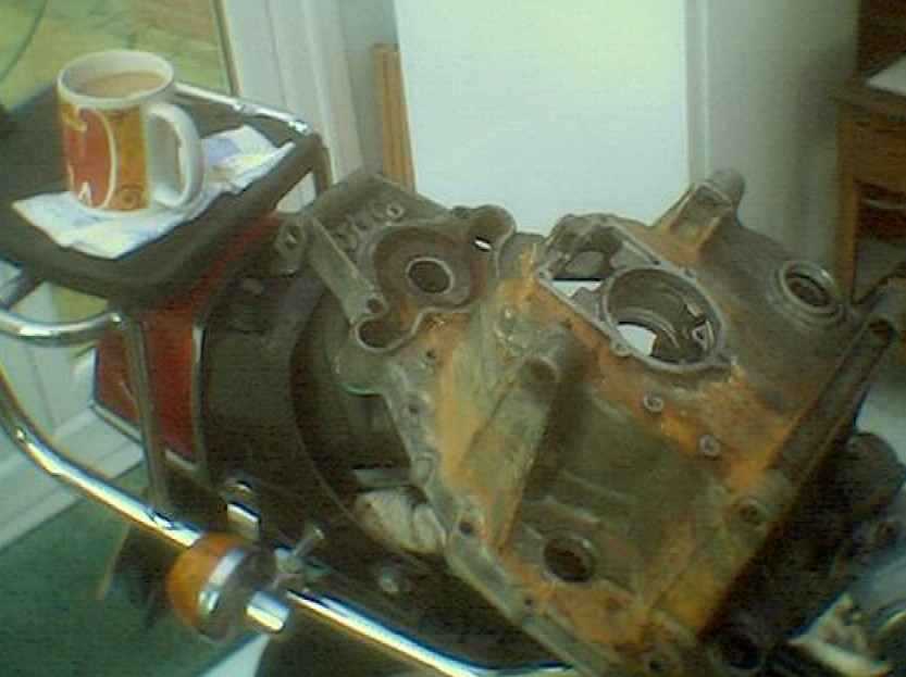
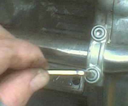 If
you didn't do this during the engine removal, remove the two clamps which hold
the chrome water transfer pipe to the bottom left hand face of the engine (left).
There are 4 Allen screws which hold the clamps in place. Pull the pipe away
from the body of the water pump and drain off any coolant remaining. There will
probably be a spillage at this point. The transfer pipe is a push fit into the
water pump casing, and has a sealing O ring.
If
you didn't do this during the engine removal, remove the two clamps which hold
the chrome water transfer pipe to the bottom left hand face of the engine (left).
There are 4 Allen screws which hold the clamps in place. Pull the pipe away
from the body of the water pump and drain off any coolant remaining. There will
probably be a spillage at this point. The transfer pipe is a push fit into the
water pump casing, and has a sealing O ring.
Pull off the thin rubber pipe from
the top of the water pump body.
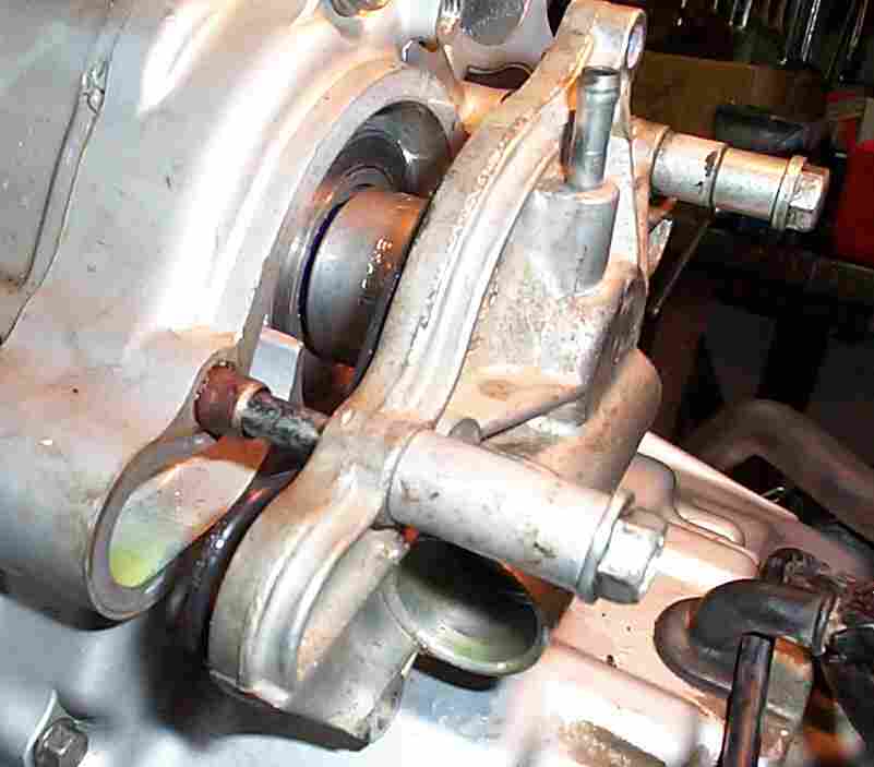
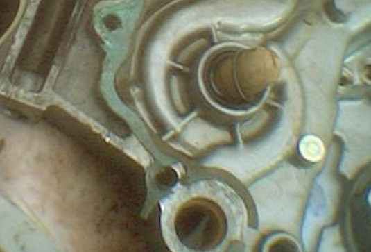
 The
water pump casing and body is held onto the rear of the crankcase by 2 x 14mm
head bolts and 3 x 8mm head bolts (right), one is quite well hidden under the
leftmost bottom edge of the body. Always use an 8mm socket, as these little
bolts are quite soft, and are easily rounded off if you try an open ended spanner.
The
water pump casing and body is held onto the rear of the crankcase by 2 x 14mm
head bolts and 3 x 8mm head bolts (right), one is quite well hidden under the
leftmost bottom edge of the body. Always use an 8mm socket, as these little
bolts are quite soft, and are easily rounded off if you try an open ended spanner.
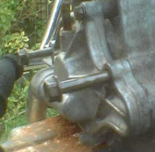
 The
pump body can be a stubborn fit. Give it a series of taps all round with a soft
rubber mallet to loosen it, and using a broad bladed screwdriver, gently
prise it away (left and right) from the rear engine casing.
The
pump body can be a stubborn fit. Give it a series of taps all round with a soft
rubber mallet to loosen it, and using a broad bladed screwdriver, gently
prise it away (left and right) from the rear engine casing.
 Be
very careful not to warp the aluminium casings, and as the body starts to come
clear, don't force the blade into the gap and twist, or you'll distort something.
Patience is the key here.
Be
very careful not to warp the aluminium casings, and as the body starts to come
clear, don't force the blade into the gap and twist, or you'll distort something.
Patience is the key here.
 Once
the body is free, store it with its five bolts.
Once
the body is free, store it with its five bolts.
Remove the 10mm dome nut and the
brass washer from the end of the camshaft, and pull off the impeller rotor.
This also can be a stubborn fit, and again the key is patient gentle teasing
with a broad bladed screwdriver. If you break off the end of the camshaft, you
are in serious trouble!
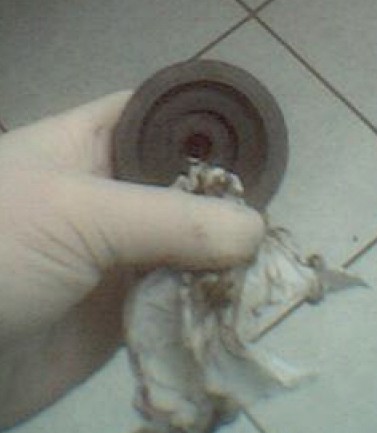
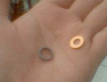
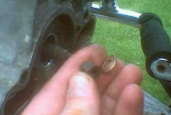 Don't
lose the copper washer and the dome nut (right) and once you've wire-brushed
the impeller clean, store all these pieces safely. I often store related components
in clear plastic sandwich bags, label them and tie the necks. It's best to replace
the copper washer. Just inside the flat face of the impeller is a thicker, steel
thrust washer, don't lose this as it's important. It sits right inside the rubber
boot which holds the ceramic seal.
Don't
lose the copper washer and the dome nut (right) and once you've wire-brushed
the impeller clean, store all these pieces safely. I often store related components
in clear plastic sandwich bags, label them and tie the necks. It's best to replace
the copper washer. Just inside the flat face of the impeller is a thicker, steel
thrust washer, don't lose this as it's important. It sits right inside the rubber
boot which holds the ceramic seal.
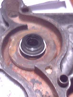
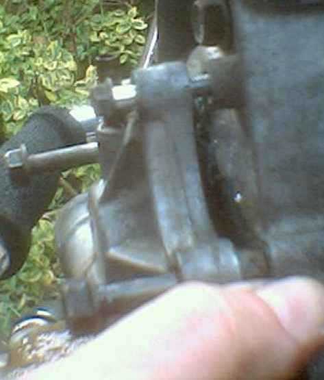
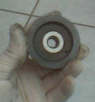
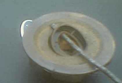
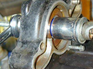
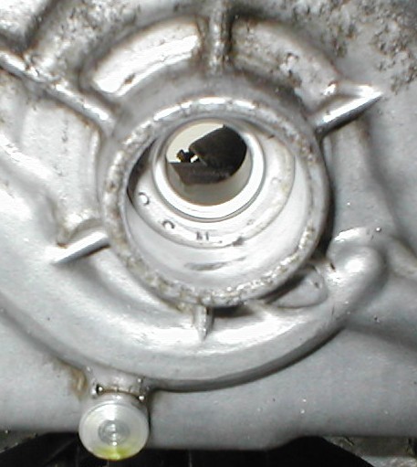
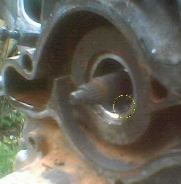 Water
pump area, showing (ringed, left) the overflow hole. This is where the weep
comes from. As the mechanical seal fails, coolant leaks past it and drains down
the little overflow passage, onto the left hand side of the rear crankcase cover,
your left boot, and the H-box. As you can easily see from the photo, this is
what happened here.
Water
pump area, showing (ringed, left) the overflow hole. This is where the weep
comes from. As the mechanical seal fails, coolant leaks past it and drains down
the little overflow passage, onto the left hand side of the rear crankcase cover,
your left boot, and the H-box. As you can easily see from the photo, this is
what happened here.
Once all the bolts are removed from
the rear crankcase cover, tease the cover away from the engine main section.
Try not to disturb the gearshift mechanism, as it's a little troublesome to
re-engage it properly and it's best left alone unless you want to dismantle
it for some reason.
Pull the oil seal out with a pair
of pliers. If you haven't yet removed the remains of the old mechanical seal,
insert something like a socket extension from the inside of the crankcase, locate
it on the rim of the mechanical seal, and tap it smartly with a hammer, taking
care not to score or damage the aperture.
The rear casing needs to be completely
stripped of all components. The page on replacing
the stator tell you how to do this.
Once the rear casing is stripped,
offer up the new mechanical seal to the aperture and see if it is obviously
too big. (See the note at the top of the page about there being two different
aperture sizes). If it looks as if it will go in, wash and degrease
the casing thoroughly (I put mine in the dishwasher, with no ill effects) and
then heat your domestic oven up to 250 degrees C and place the casing inside.
Most of us wait until the wife is out before we do this.
If you don't completely clean and
degrease the cover before heating it, the smell of burning oil is vile ... and
the wife will know what you've been up to!
Leave it for an hour or so, and with
your 28 mm socket and new mechanical seal ready, remove the casing and place
it open or engine end down on a firm, flat surface. Smear some gasket sealant
round the circumference body of the mechanical seal and position it squarely
into the aperture from the outside inwards.
Place your socket over the seal
so that the socket's edge bears on the outer lip of the seal, and with careful
taps of a rubber hammer, knock the seal into its housing. Be especially careful
to keep the seal square on to the crankcase so that it goes in dead straight.
Once it's fully home, allow the casing to completely cool, and as the metal
shrinks, the seal is held in the housing. Don't use any pressure or force on
the central part of the mechanical seal as this is particularly fragile. When
fully home, the seal's outer lip engages with the aperture in the casing, and
it's very obviously fully in.
Check that the drain is clear - I
used a short length of coat hanger wire. Check that no gasket sealant is obstructing
the drain hole at the water pump end.
Insert the new oil seal with its
closed face towards the mechanical seal.
Before refitting the gearbox output
shaft bearing, spin it round close to your ear and listen for any crackling
or scraping. Likewise feel for any unevenness. If it shows any sign of stiffness
or grating, replace it. These bearings are very robust and a failure is unlikely.
Reassemble the rear crankcase components,
using a new camshaft oil seal, which goes in with its closed face inwards, facing
the mechanical seal (diagram at the top of this page); and a new shaft drive
oil seal and gearshift oil seal. The latter both drift in from the outside.
Refit the rear cover, as per the stator change
page. Put the gearbox into first gear, to hold everything still as you replace
the cover.
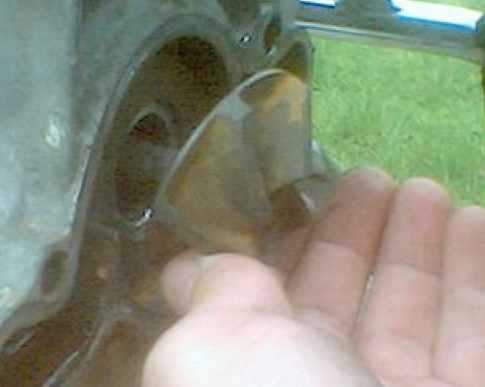
 Clean
the impeller rear flat face (left) and the rear crankcase water pump area, and
fit the thrust washer over the end of the camshaft. In the photo (right) the
new thrust washer and brass washer are shown.
Clean
the impeller rear flat face (left) and the rear crankcase water pump area, and
fit the thrust washer over the end of the camshaft. In the photo (right) the
new thrust washer and brass washer are shown.
The ribbed thrust washer is VITAL
and the most important washer on the whole bike! So don't think you can get
away with omitting it, if you try this, or forget to fit it, the mechanical
seal will leak.
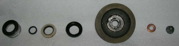 Seal
parts left to right : mechanical seal, steel splined washer, polo mint, rubber
boot, impeller, copper washer, dome nut.
Seal
parts left to right : mechanical seal, steel splined washer, polo mint, rubber
boot, impeller, copper washer, dome nut.
(Thanks to Jim Nelson for the
photo.)
 Impeller
with the new rubber boot and ceramic seal face, what I call the Polo Mint seal
(right).
Impeller
with the new rubber boot and ceramic seal face, what I call the Polo Mint seal
(right).
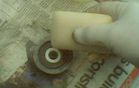 Soap
the rear face of the ceramic seal (left) before fitting the impeller, to lubricate
the seal until the pump is delivering coolant to the components.
Soap
the rear face of the ceramic seal (left) before fitting the impeller, to lubricate
the seal until the pump is delivering coolant to the components.
It's absolutely vital, for the psychological
welfare of your bike, to do this with a cake of Imperial Leather!
Fit the thrust washer, impeller with
its flat face towards the rear casing, the brass washer, and then the dome nut.
Tighten the dome nut to 6½ ft lbs (0.8 - 1.2 kg/m). Again NEVER try this
without a torque wrench as the stem of the thread is thin and easily overtightened.
If you snap it off you will have to strip the engine and replace the camshaft
- and CX camshafts are rare.
Refit the engine as per the engine
removal page. Don't run the engine without coolant, and check carefully
for leaks. When refilling the radiator, use a 50/50 mixture of distilled or
deionised water (battery water) and silicate-free antifreeze,
with its distinctive pink colour. Silicate-free antifreeze is much better for
the ceramic seal and cooling system generally. UK readers note that if you buy
antifreeze from Halfords, it should be the more expensive "Advanced"
formula, which does actually say silicate-free on the rear of the bottle.
The O-ring at the water pump end
of the chrome pipe has a compatible replacement which is easily obtained from
any UK Homebase DIY store's plumbing section. The part is Homebase 6 pack Assorted
Small 'O' Rings, 5013669158680, Article 623904, £1.09.
I found that the water transfer pipe
needs rather careful handling during refitting. It locates quite easily at the
radiator end, but the water pump end has a double ridge, between which sits
the O-ring. As the pipe is inserted fully home into the aperture of the water
pump casing, it's quite a tight fit and the O-ring tends to deform. Then, it
either gets trapped between the ridges and the casing, usually cutting it, or
gets pushed right off along the pipe. Either problem will cause a water leak.
The O-ring sits between the two ridges
on the chrome pipe's end. Smear a little grease all round the O-ring as a lubricant
during reassembly. Also, tease the pipe's end into the casing very cautiously,
checking with a lamp that the O-ring hasn't deformed. I used a very narrow screwdriver
to gently push the O-ring along all round its shape, with the pipe as I inserted
it.
When the water transfer pipe is fully
home, its sits correctly in the two mounting points on the left hand lower crankcase.
If it isn't locating fully at these two places, it's displaced, probably because
it's not fully inserted into the water pump casing.
If it does leak afterwards, just
slip it out and examine / change the O-ring. A leak here looks like a bad mechanical
seal, but it isn't. Don't panic.
Incidentally I have sourced the water
transfer pipe and junction-to-cylinder-head o-rings at 20 pence each and I bought
a dozen each of these for a fiver all inclusive. If you need these o-rings,
contact Seals and Components Ltd, Village Road, Norton, Shifnal, TF11 9ED, Shropshire.
Tel: 01952 730685. Fax: 01952 730665. The larger o-rings which seal between
the 90-degree water junctions to the cylinder heads are BS-119 and the smaller
and slighltly thinner ones which seal each end of the watertransfer pipes to
the thermostat and junctions are BS-118.
Additional Photographs
Inside the rear casing.
 Valiant's
old ceramic seal being prised out of its rubber boot. Note the score marks -
the seal is knackered!
Valiant's
old ceramic seal being prised out of its rubber boot. Note the score marks -
the seal is knackered!
 The
rubber boot being lifted away. The previous spannerman hadn't bothered to refit
the thrust washer, which is probably why the seal was knadgered at only 42,000
miles.
The
rubber boot being lifted away. The previous spannerman hadn't bothered to refit
the thrust washer, which is probably why the seal was knadgered at only 42,000
miles.
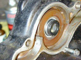
 Knackered
rear camshaft seal, seen prior to removal. This is the inside face of the rear
casing, showing the seal correctly fitted with its closed face towards the mechanical
seal. The best way to get this seal out is to insert a socket from the other
side, and simply tap it free.
Knackered
rear camshaft seal, seen prior to removal. This is the inside face of the rear
casing, showing the seal correctly fitted with its closed face towards the mechanical
seal. The best way to get this seal out is to insert a socket from the other
side, and simply tap it free.
 When
I poked my gloved finger through from the water pump side, the oil seal disintegrated.
Imagine the fun if this spring ring had come off and wrapped round the camshaft
...
When
I poked my gloved finger through from the water pump side, the oil seal disintegrated.
Imagine the fun if this spring ring had come off and wrapped round the camshaft
...
 The
stained rear crankcase after stripping. Notice the most important accessory
of all, which is seen here on Valiant's rear carrier!
The
stained rear crankcase after stripping. Notice the most important accessory
of all, which is seen here on Valiant's rear carrier!
Ian
Shearer makes some useful comments : "I just put in a mechanical
seal and decided to try it without heating the casing, as the Honda manual says
to just press it in with the special tool, and I couldn't honestly see why heating
would be required. Here are some photos of how I pressed the new one in. I used
the same method to pull the old one out, and then I put the old one back in
again for practice. It seemed OK, so I went ahead and pressed in the new one.
The casing diameter was 28mm. Bike is a 650 Eurosport."
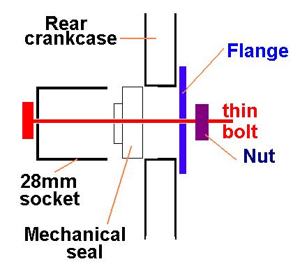 Diagram
of the home-made insertion tool. The thin bolt is slim enough to pass through
the mechanical seal (where the camshaft tail pokes through to drive the water
pump) and as the nut is tightened, the socket bears against the mechanical seal
lip, and pulls it into the crankcase aperture. The flange just spreads the load
over the inner surfaces of the crankcase.
Diagram
of the home-made insertion tool. The thin bolt is slim enough to pass through
the mechanical seal (where the camshaft tail pokes through to drive the water
pump) and as the nut is tightened, the socket bears against the mechanical seal
lip, and pulls it into the crankcase aperture. The flange just spreads the load
over the inner surfaces of the crankcase.
 Removing
the old seal.
Removing
the old seal.
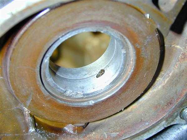 Close-up
of the seal aperture, showing where a previous seal change has damaged the rim.
Close-up
of the seal aperture, showing where a previous seal change has damaged the rim.
The drain hole is clearly seen in
this photo.
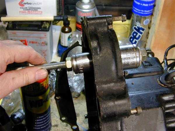
 Pressing
in the new seal, using the home made tool, and without heating the rear crankcase
cover.
Pressing
in the new seal, using the home made tool, and without heating the rear crankcase
cover.
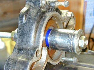
 The
new seal fully inserted into the aperture.
The
new seal fully inserted into the aperture.
 Job
done, at (says Ian) "an ambient temperature of 8C".
Job
done, at (says Ian) "an ambient temperature of 8C".
When refitting the rear cover, don't
insert or tighten the bolts until the action of the gear lever is found to be
correct. It's extremely easy to dislodge the gear level actuating teeth whilst
easing the rear cover into place.
MANY THANKS to Ian for taking the
trouble to photograph as he went along.
More useful stuff from the
late Rick Hoad of Derby
 "If
you have the smaller 27mm aperture, use a 30mm flap wheel and power tool to
gently ream out the orifice to accept the Yamaha seal. Flap wheels don't grind
the metal away like an abrasive wheel would."
"If
you have the smaller 27mm aperture, use a 30mm flap wheel and power tool to
gently ream out the orifice to accept the Yamaha seal. Flap wheels don't grind
the metal away like an abrasive wheel would."
BE VERY CAREFUL not to run the
flap wheel in deeper than the drain hole!
If you open the aperture all the
way through, you are also widening the hole for the oil seal - and it won't
seal. Don't ask me how I know this ... aaarrrgggggggghhhhhhhhhhh !!
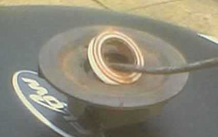
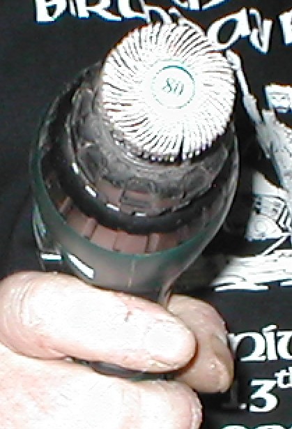
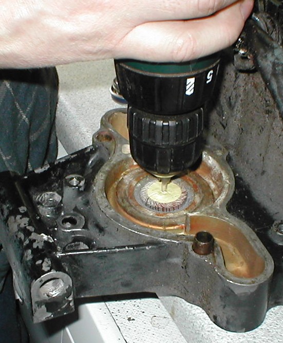 "Here
you can see the 30mm flap wheel inserted into the orifice and it very gently
eases out the diameter of the aperture."
"Here
you can see the 30mm flap wheel inserted into the orifice and it very gently
eases out the diameter of the aperture."
 "View
from the inside face of the rear crankcase, showing the mechanical seal correctly
inserted."
"View
from the inside face of the rear crankcase, showing the mechanical seal correctly
inserted."
Thanks to crack spannerman (the late
Rick Hoad) for these invaluable tips.
You are welcome to comment
on these pages.