 Left
and right are as you'd see them from the normal riding position.
Left
and right are as you'd see them from the normal riding position.CX / GL 500 / 650 Alternator and Stator Health Check
Stator Remove / Refit
and the "White Wire Fix"
Skill Level : 1. Dirty Level : 1. Work Mess Level : 1. Tools level : (special) : multimeter. You cannot check or diagnose a stator without a multimeter, but they are useful tools, and it's worth buying one and learning how to use it. Space required : 1. Time : expert 10 minutes, average 15 minutes, "first-time" 20 minutes.
All the hands, tools, and bike in the photos are the author's.
I am very receptive to comments and suggestions, but you use these pages entirely at your own risk.
All nut and bolt sizes are quoted as the spanner size required to fit them.
I have a very comprehensive Word document which is an electrics faultfinding chart, please ask you would like a copy (365k zipped or 522k plain).
This page will show you how to check the output voltage from the stator on your CX / GL engine. It can be done whenever desired, or whilst investigating a misfire.
The stator is located inside the rear engine casing and is a halo-shaped wiring coil with several individual circuits providing various functions. The current from it is produced by the alternator rotor, which is bolted to the rearmost section of the crankshaft, revolving rapidly around the stator as the engine runs.
The CX and variants engine is prone to partial stator failure as the bike ages, mainly due to the conditions of heat and oil in which the stator lives. The Turbo models are especially likely to suffer, as these engines run rather hotter than the normally aspirated types. Whilst diagnosis is simple, replacing a stator does mean removal of the engine and rear crankcase cover. However, if your stator has failed, there is a good get-you-home or short term "fix".
Am I CDI or Transistorised ignition?
The general rule is that the 500s except the GL500 and CX500E-C Eurosport have CDI ignition and all the rest, including all the 650s, have transistorised ignition. However the model is so old that many bikes have engine transplants!
The easy way to check is to:-
> look under the saddle. Just behind the air intake is either a gold or black box, about the size of a packet of 20 cigarettes. If this is present and connected up, you have CDI ignition (see photo lower down).
> look behind the left hand side panel. Just behind the battery, if you can see two identical silver ribbed boxes each about the size of a matchbox, you have transistorised ignition.
This diagnosis ONLY applies to CDI ignition bikes.
Symptoms
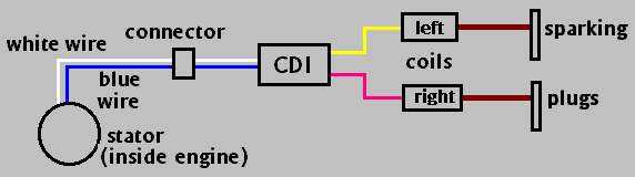
For the purposes of generating the voltage required to trigger the CDI (capacitor discharge ignition) unit on your bike, which then via the ignition coils and sparking plugs, generates the spark which fires the engine, there are two independent circuits contained inside the stator (diagram below). One provides a minimum of 90 volts up to between 4,500 and 5,000 rpm; this is the low circuit with the white wire. Its partner with the blue wire operates the high circuit above this engine speed, and produces a voltage of at least 100 volts. On the CX engine, partial stator failure is indicated by the engine refusing to rev much above 5,000 rpm (if the high circuit has failed) or below 5,000 rpm (if the low circuit has failed).
Left
and right are as you'd see them from the normal riding position.
Misfiring has many causes, not necessarily due to a bad stator. So, before committing hari-kari, removing your engine or starting other major operations, try the following:-
> install new sparking plugs. I have had a misfire which had me thinking "Oh no, a stator change" but new plugs solved the problem. I use NGK DR8ESLs on my 1981 UK CX500A, and regard 3,000 miles as a maximum lifespan for plugs. I ALWAYS carry spare plugs. I've recently tried a pair of D8EAs and found that these work a little better than DR8ESLs. Also try new plug caps.
> faulty ignition coil. Having had the dreaded 5,500 - 6,000 rpm misfire, where the engine bogs down, I checked the stator voltages and found they were at the minimum. So I had a spare stator professionally rewound, and fitted it. The engine was very much improved, until during a heatwave, the misfiring returned. After swapping out the spare CDI unit and the left hand coil, to no avail, I replaced the right hand coil and the problem went away. It seemed that ambient temperature of 25C+ (which is a heat wave in the UK!) added to the residual engine heat, was too much for the coil, which was probably nearing the end of its life.
> disconnect the undersaddle electrical blocks and thoroughly clean both halves, getting a wire cleaning brush right into the male and female connectors. Then spray with WD40 and wrap the connectors in cling film or a plastic shopping bag, to keep out dirt. I also cured what I thought was a stator failure, by cleaning the connectors, which had simply accumulated dust and dirt.
> check that there is no electrical shorting (arcing) between the ignition coils and earth, particularly against the main spar, or between the high tension plug leads and the engine. This can be a very subtle fault and is best investigated in complete darkness whilst the engine runs. Any arcing is much more easily spotted in darkness. Check that the red engine kill switch doesn't have something sparking merrily inside it - on the dark, you can see this easily.
Dave in Atlanta, Georgia USA had a new Electrex stator fail and had posted details here. My own experience of Electrex stators has been bad and I don't recommend them. Details of recommended stator suppliers are further down the page.
Diagnosis
This diagnosis can ONLY be carried out with a fully charged and functional battery. If your battery is suspect, you should replace it, or the voltages you are trying to read may well be incorrect.
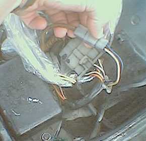
Remove the saddle and locate the set of three male-to-female connecting blocks just by the air filter box. The one in question is the only two-wire one, a white wire (the low current) and the blue wire (the high current.) In the photo (left), I've lifted out the the stator connector. Notice the plastic sheeting which I have wrapped round the three connectors, to keep out dirt and muck; and the CDI unit in the bottom left part of the picture. Some variants have gold-coloured CDI units instead of the black one shown here; the two boxes are interchangeable.
Remove the sparking plugs. Turn off the fuel and turn on the ignition. Ensure the gearbox is in neutral.
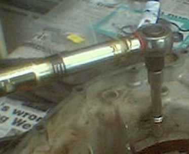
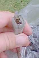 Disconnect
the white / blue wire connector and make sure that you have the male end (right)
which leads to the alternator.
Disconnect
the white / blue wire connector and make sure that you have the male end (right)
which leads to the alternator.
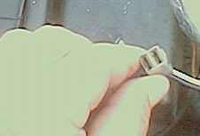
The other, female end (left) goes to the CDI unit, which is the dull black box directly behind my fingers.
Set your multimeter to read a range between 60 and 250 volts AC, and put the positive pin of the multimeter on the spade connector of the white wire circuit and the negative pin of the multimeter to any convenient earth point, perhaps the engine or even the negative terminal on the battery.
Spin the engine on the starter motor and watch the reading on the multimeter. On the white or low current wire, you should get a reading of about 90 volts AC. Remember that the battery must be fully charged.
Now swap the positive lead from the multimeter to the blue, high current wire; leave the other terminal from the multimeter on the earthing point. Turn the engine again on the starter motor. The reading should be about 100 volts AC.
REMEMBER : White Wire about 90 volts : Blue wire about 100 volts, AC. ("Whitey ninety, bluey highey")
If either reading is below par, it means that particular circuit has failed or is failing. If the stator is on the way out, the voltage reading will drop as the engine revs higher. This is because cracked insulation on the stator, or simply old age, is causing the electrical power to "leak".
So, how low is low? If the white is less than 70 volts or the blue is less than 90, your stator is tired. Some readers have commented that their bikes run well with as little as 60 volts output on white, but this does show that the stator is definitely living on borrowed time. If the engine is due to come out anyway - change the stator.
Also use your multimeter to check that none of the wires have a continuity to earth. Any earthing on the white, blue or yellow circuits shows that the stator is defective. An earth return on any of the yellow wires means that the stator is not properly charging the battery.
Detailed Diagnosis
Your multimeter can be used to check the resistance of the two stator circuits. The low (white) charging coil is grounded with its lower end. The high (blue) charging coil with its lower end is connected in series to the low coil upper end, and that's the point where the white wire is connected. The upper end of the high coil is connected to the blue wire. Both the white and blue wires end in the 2-pin block connector.
Stator failure can cause misfiring and power loss even with the blue and white voltages well within the limits - so check the resistances as well as the voltages! There have been a handful of cases where a stator has been measured at ot close to the correct voltages, but for some undefined reason does not work correctly. You can try a white wire fix if all else fails.
If the voltages are down so much that the blue level is not much more than the white level, you can even do a blue wire fix - i.e. disconnect the white wire and patch the blue wire to both inputs to the CDI unit. HOWEVER don't do this if the blue voltages are normal as the extra power will damage the system.
The earth, or ground, signal coming from the stator is the green line at the big (8-1 pin) block connector.
To test these values, set your multimeter to measure resistance and the readings between the wires should be as follows:-
|
Between
the
|
and the
|
Lowest
resistance (ohms)
|
Highest
resistance (ohms)
|
|
Green
|
White
|
387
|
470
|
|
Blue
|
White
|
77
|
99
|
|
Blue
|
Green
|
should be
the other two values added together.
|
|
This Multimeter Readings chart may also help with diagnosing the source of
a problem:-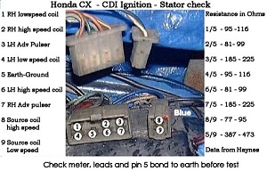
Klaus Werner kindly made some useful comments to this page, and he says "The tolerances above are quite big. My CX500 Custom has 387 for low coil, but only 73 for high coil, but runs well. One problem measuring the values is, that you need to get proper contact by the measuring tips, since most of the tips are not really sharp and the wire and contact surfaces of this old equipment is corroded. Instead of the standard tips coming with the instrument, one should buy professional tips, which are really sharp pointed. When measuring high voltages this does not matter, but for measuring low resistances it is essential. The low currents and voltages used for the latter don't 'break' any insulation caused by corrosion."
He continues "You can also check the output from the alternator charging circuit, by measuring continuity of the main power coils on the 3 yellow wire undersaddle connector. With this connector disconnected, none of the wires must have any connection to ground, otherwise the 3-phase generator has failed."
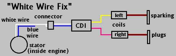
The White Wire Fix - a 'get you home' tip
If the blue (high current) has failed, your bike will be very reluctant to rev much about 5,000 rpm which will restrict your speed to about 50-55 mph. Changing the stator will of course fix this, but there is a get-you-home or short-term fix for the problem, only if the blue or high circuit has failed.
Cut the blue wire 1" back from where it arrives from the alternator to the connector box and insulate it, taping it out of the way. Patch the stub of the blue wire from the connector box to the white wire's connection at the box. This takes the low current and sends it to both circuits. It isn't enough to give full high power to the CDI unit, but it does give much better performance than nothing at all. It is also recommended to reduce the sparking plug gap by 2 thousandths of an inch, to give the spark a shorter jump and less work to do.
I have recently had a case where the engine misfired on one cylinder, the stator voltages checked out within the specified voltages, but a resistance test showed other faults. This was "cured" with the white wire fix, but a new stator is the proper answer. The white wire fix has apparently been used for months at a time with no ill effects, but the only true remedy is to bite the bullet and remove the engine, rear cover, and change the stator, or at least have it professionally rewound. If you're going to do that:-
> replace the cam chain, its guide blade, tensioner blade and spring if the old ones have done more than 20,000 miles;
> replace the mechanical seal if the old one is leaking or has done more than 20,000 miles.
However, don't do a "blue wire fix" as the 100+ volts from the high circuit will damage the CDI unit if that much voltage is fed down the low (white) line.
I have a full schematic diagram of the CDI unit, which I'll email on demand.
Don in Australia,on the subject of testing stators without having it fitted to the engine, says:-
"You can really only be certain about the CDI section - after resistances and insulation measurements - by running it in a bike. I have repaired at least eight CDI stators until they all met the above referred figures, and they all worked in motors, but I wasn't happy with the repair until the motor had fired up and I had measured voltages - with an oscilloscope."
The Ignitech alternative
There is good ndews for CX owners whose stators have become tired, with reduced voltages, affecting performance.
A company based in the Czech Republic makes an alternative for the CDI and the REALLY good news is that installation is very simple, does NOT require dropping the engine, and can be done in under an hour. The Ignitech unit is the same size as the CDI and draws its power from the rear brake light circuit and its signals from the advance pulsers. It doesn't use the blue and white power feeds from the stator.
My stator showed reduced voltages in summer 2014 and an Ignitech unit was fitted quite painlessly. There was a distinct, but not dramatic improvement in performace, with better engine response at low / mid range revs and improved fuel consumption. However as the Ignitech needs a a functional 12v power feed to work, you can't bump-start the engine if the battery is completely flat. But this is a tiny disadvantage compared to not having to drop the engine and change the stator.
The cost of the Ignitech is rather less than what a rewound exchange stator will cost you - and no engine work - it's a no brainer! Here is a video on the unit.
You can contact Ignitech via their web site, they do speak English if you enquire via email.
IgniTech
Ceskobratrska 84
535 01 PRELOUC
Czech Republic
[email protected]
www.ignitech.cz
Stator Rewinds - if you really want to do it ...
I have been informed of the following companies who sell new stators and do stator exchanges. Please advise me if you are given updated prices.
|
Bernt Muhl, Muhl CX500-Shop, Jahnstr. 5, 21435 Stelle, Germany (Stelle is 8 miles SSE of Hamburg, in Saxony)
|
||
|
Model
|
Type
|
Price
Euros
|
|
CX500 - 82
|
Exchange (send
your old stator)
|
172.50 + 15 freight |
|
CX500 82 (CX500E
/ GL500 etc)
|
Exchange (send
your old stator)
|
149
+ 15 freight
|
|
CX500 82 (CX500E
/ GL500 etc)
|
New stator
|
193.50
+ 15 freight
|
|
Freight charges
quoted are to the UK. Enquiries from other countries are welcomed.
|
||
|
Hadler's Garage PM Ltd, 198-200 Baddow Rd, Chelmsford, Essex CM2 9QP, UK. 01245 354844 (30 miles ENE of Central London)
|
||
|
Model
|
Type
|
Price
Sterling
|
|
CX500
|
Exchange (send
your old stator)
|
£76.38 inclusive as at 11-Jul-03 |
|
West Country Windings following several failures and disappointments, this company is no longer recommended. |
|
Custom Rewind, 2014 Pratt Highway. Birmingham, Alabama, USA 35214. Phone 1-800-798-7282 and talk with Gary |
||
|
Model
|
Type
|
Price
US Dollars
|
|
CX500
|
Exchange (send
your old stator)
|
US$ 240 including
shipping
|
|
"Bert"
(owner), Small Coil Rewinds, 50 Edols Street, North Geelong, Vic., 3215.
Australia. |
||
|
Model
|
Type
|
Price
US Dollars
|
|
CX500
|
Exchange (send
your old stator)
|
AUS$ ???
|
Stator Removal / Replace
If your stator needs replacing, this is how you do it.
Skill level (after engine removal) 1. Personally dirty : 1. Work mess : 1. Tools : 1. Space : 1
Time (after engine removal) expert 15 minutes, average 25 minutes, "first time" 35 minutes.
"Drift in / out" means to use a tool such as a socket, or metal pipe, to act as an agent between the object being removed / replaced and the hammer or mallet. The drift should be a very close match to the outer diameter of the object, and prevents damage to it, only allowing force to be applied to its outer edge. For example, a bearing is often a very tight fit in its space, and to bang it with a hammer would damage it or its aperture. Using a drift over the bearing allows force to be applied to only its edge.
Remove the engine from the frame. If you are replacing the stator, you are strongly advised to:-
> change the cam chain and tensioning apparatus if these have done more than 30,000 miles. There are additional pictures of these components are on the "engine out" and "decoke" pages. This advice applies whether you have a manual tensioner (all 500s except Eurosport) or an automatic tensioner (500 Eurosport, all 650s, all Turbos).
> replace the water pump mechanical seal and camshaft rear oil seal if these are weeping, or have done more than 20,000 miles. Mechanical seal failure is indicated by a coolant leak (the dreaded brown stain) over the rear left crankcase cover.
Both these jobs can ONLY be done when the engine is removed, with the rear crankcase cover is off. Working on the tried and tested principle of Sod's Law, the week after you change the stator, your mechanical seal will start weeping. As you have to strip the rear crankcase bare before changing the mechanical seal, for the sake of a tenner and another hour's work, you might as well do it now.
Naturally you will replace all rear crankcase gaskets and seals, these are best bought as a complete kit. But you can buy 0.8mm gasket roll from Ebay and cut your own crankcase gaskets, for next to nothing! I've made lots of these and never had one leak.
Remove the water pump housing and impeller.
Before you start, lay the engine face down (ie on the fan or radiator end) on a thick towel. It's easier to work on the engine this way, and any fluid will drain forwards into the engine casings, rather than leak out onto your work area. But some coolant and oil drips are inevitable.
Remove the 8mm and 12mm head bolts which secure the rear crankcase cover to the centre section. Using a rubber hammer or a block of wood, tap the rear casing sharply all round its circumference, to free it. Usually it sticks around the "shoulders" where the water transfer passages are, either side of the water pump base. The crankcase metal is VERY thin around the passages area, so don't use any lever force here.
If the casing won't come off, tap it with your rubber hammer or wood block at the very top, above the water pump casing, where the top holding bolts attach to the frame. Later models don't have this bracket and the rear casing is different. In this case, lever very cautiously between the middle engine section and the rear. Don't poke a screwdriver into the aperture as it opens up, or you'll damage the mating surfaces.
As the rear cover comes free, push inwards on the gear shift arm so that it stays in place, engaged with the mechanism at the bottom of the centre engine section. Leave the shaft drive in place.
Clean off all traces of the old gasket from both casings. Discard the two O rings around the water transfer passages.
I will work on the basis that the rear cover is to be stripped down and a new mechanical seal fitted. If not, omit the sections starting with an asterisk.
Disconnect the neutral light lead. This exits the thick wiring harness close to the engine casing and runs behind the casing to a connector immediately below the shaft drive output.
Remove the rear ignition pickup cover.
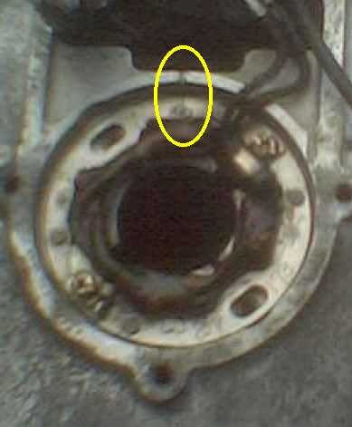 *See
that on the pickup ring, there is a small index mark (ringed) at 12 o'clock
which marries up with a slot in the engine casing. Normally these two marks
are in perfect alignment, but if yours is not, make a careful note of how the
ring is aligned to the casing. It this adjustment which allows the ignition
timing to be adjusted - which isn't normally necessary.
*See
that on the pickup ring, there is a small index mark (ringed) at 12 o'clock
which marries up with a slot in the engine casing. Normally these two marks
are in perfect alignment, but if yours is not, make a careful note of how the
ring is aligned to the casing. It this adjustment which allows the ignition
timing to be adjusted - which isn't normally necessary.
Models with transistorised ignition have a mechanical timing mechanism appended to the rearmost section of the crankcase.
 Peel
off any silicon gel and disconnect the ignition pickup ring's two connectors.
Peel
off any silicon gel and disconnect the ignition pickup ring's two connectors.
 *The
pickup ring (right) is held in place by 2 crosshead screws and you may need
an impact driver to dislodge them. Remove the ring.
*The
pickup ring (right) is held in place by 2 crosshead screws and you may need
an impact driver to dislodge them. Remove the ring.
Pull away the two rubber grommets at the top of the rear casing, and feed the thick electrical cable through the small aperture so that all the wiring is "inside" the engine casing.
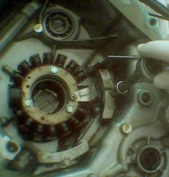 Remove
the left and right ignition sensors, each held in place by one 10mm head bolt.
Loosen them from their mountings, they are attached to the stator, so don't
pull them off.
Remove
the left and right ignition sensors, each held in place by one 10mm head bolt.
Loosen them from their mountings, they are attached to the stator, so don't
pull them off.
Transistorised models don't have these two sensors - but may still have the mounting and screw holes to accommodate them!
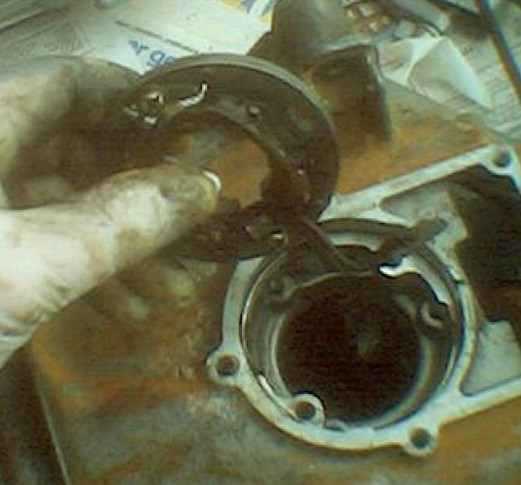
 Remove
the three 10mm head bolts holding the alternator stator, and remove it with
the attached sensors.
Remove
the three 10mm head bolts holding the alternator stator, and remove it with
the attached sensors.
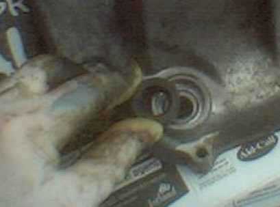
*Pull off the shaft drive oil seal flange, this comes off backwards.
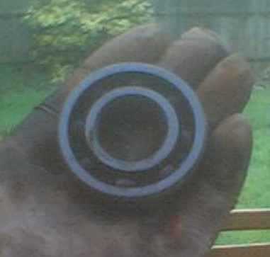
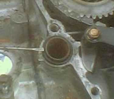
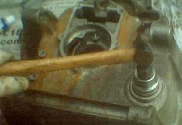 *Drift
out (left) the shaft drive crankcase bearing (right) from the outside, inwards.
*Drift
out (left) the shaft drive crankcase bearing (right) from the outside, inwards.
This was a 27mm socket used as the drift.
Drift out the gearbox oil seal.
*Visually check that the rear crankcase cover is completely free of all fitments and components.
*Fit the mechanical seal and camshaft rear oil seal.
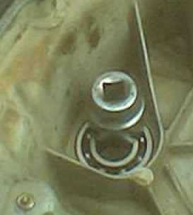
 *Drift
in the shaft drive crankcase bearing (you may find this easier to do whilst
the casing is still hot) from the inside outwards, and refit the shaft drive
oil seal flange (right).
*Drift
in the shaft drive crankcase bearing (you may find this easier to do whilst
the casing is still hot) from the inside outwards, and refit the shaft drive
oil seal flange (right).
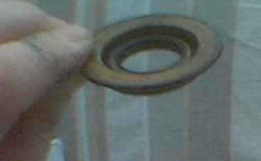
 Fit
a new gearshift oil seal. This goes in from the outside, with the flat surface
outermost (right).
Fit
a new gearshift oil seal. This goes in from the outside, with the flat surface
outermost (right).
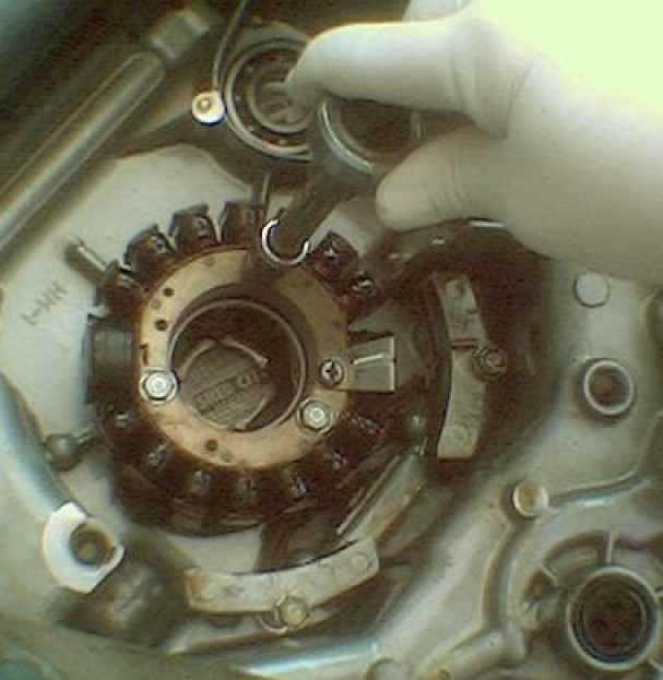
 Refit
the stator and ignition sensors. The sensors each have L and R
marked on them, as seen from the normal riding position.
Refit
the stator and ignition sensors. The sensors each have L and R
marked on them, as seen from the normal riding position.
The R one goes on the side nearer to the shaft drive bearing; the L one goes nearer to the gearshift aperture. The sensors have locating pins to ensure they are correctly aligned to the crankcase cover. Tighten the holding bolts to 7½ ft lbs.
Feed the thick cable through the narrow aperture and into the pickup ring area.
*Replace the pickup ring, paying attention to the alignment between the index mark and the slot in the upper casing.
Reconnect the pickup ring.
Reinsert the thick cable's two grommets into their slots in the upper casing.
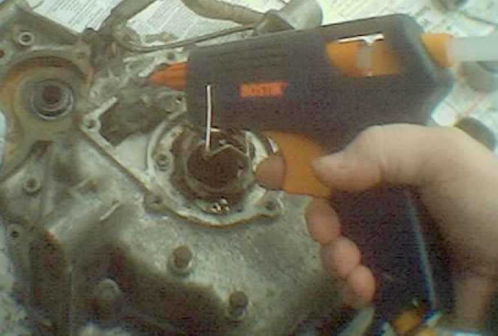 Use
silicone sealant or a glue gun to inject sealant into both this area, and the
connections between the ignition ring and the wiring harness.
Use
silicone sealant or a glue gun to inject sealant into both this area, and the
connections between the ignition ring and the wiring harness.
Replace any damaged insulating tape at the base (engine) end of the thick cable.
Reconnect the neutral light lead.
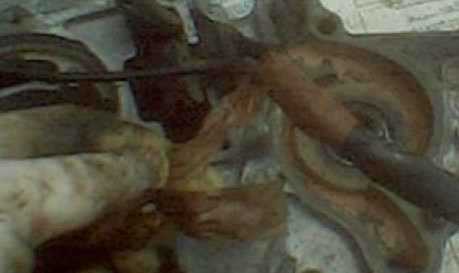
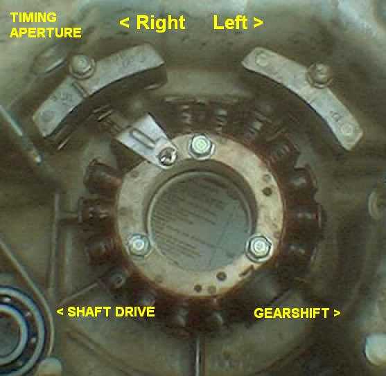 General
view (left) of reassembled stator and sensors inside the rear crankcase cover.
General
view (left) of reassembled stator and sensors inside the rear crankcase cover.
"Right" and "left" are as you would see them from the normal riding position.
I also use Hylomar or non-permanent gasket compound on both sides of the gasket; this is purely precautionary. It does help separation next time, though.
 Fit
the gasket to the engine centre section, with new O rings (left) around the
water transfer passages. Don't omit the transfer pipes.
Fit
the gasket to the engine centre section, with new O rings (left) around the
water transfer passages. Don't omit the transfer pipes.
Smear a pellet of grease over the camshaft oil seal and refit the rear casing. Fit the 8mm and 12mm bolts finger tight and then check that the gearchange mechanism works, you will probably need to turn the engine by means of the 17mm crankshaft bolt on the front casing, just below the radiator.
In a diagonal sequence, tighten the 12mm bolts to 14 ft/lbs and then the 8mm bolts to no more than 6 ft/lbs.
Smear soapy water over the mechanical seal and refit the impeller with its copper washer and dome nut, don't forget the small thrust washer which fits between the flat impeller face and the rubber base of the ceramic seal. Be careful not to damage the ceramic "Polo Mint" part of the seal. Pictures of these components are on the mechanical seal change webpage.
Tighten the dome nut to not more than 9 ft lbs. I'd recommend 7½ as if this rather thin end of the camshaft snaps off, you are in serious trouble!
Using a new curly rubber gasket, refit the water pump casing. I also use Hylomar on this.
IMPORTANT ! When refitting the rear cover, don't tighten the crankcase bolts until the gearbox action is found to be correct. Operate the gear lever whilst rotating the gearbox output shaft and check that all the gears and neutral can be selected normally. It's extremely easy to dislodge the gear level actuating teeth whilst easing the rear cover into place. This is something you don't want want to discover AFTER you've replaced and connected up the engine. Don't ask me how I know.
Refit the engine and you're done. After starting it, allow it to idle and then rev gently until warm, to check for leaks. It is common for a new mechanical seal to weep for a hundred miles or so as the two ceramic faces bed in against each other.
You are welcome to comment on these pages.